Rectangular Section Deflection Check to ACI-318M-02 Spreadsheet
30 June 2025Rectangular Section Deflection Check to ACI-318M-02 Spreadsheet
Deflection, the vertical displacement of a structural member under load, is a critical consideration in civil engineering design. Excessive deflection can lead to serviceability issues, affecting the functionality and aesthetic appearance of structures. For rectangular beam sections, a fundamental shape in various structural applications, understanding deflection behavior is paramount for ensuring safe and efficient designs.
This article provides a comprehensive overview of deflection in rectangular beam sections, outlining the key factors influencing it and the fundamental principles behind its calculation.
Why is Deflection Control Important?
In civil engineering, limiting deflection is essential for several reasons:
-
Aesthetic Concerns: Large deflections can be visually unappealing and may cause alarm to occupants.
-
Functional Issues: Excessive sag in floors can lead to cracking of brittle finishes like plaster or tiles. Deflection in beams supporting sensitive equipment can disrupt their operation.
-
Damage to Non-Structural Elements: Significant beam deflection can cause damage to attached non-structural components such as partitions, glazing, and cladding.
-
Ponding: On flat roofs, excessive deflection can lead to the accumulation of rainwater, increasing the load and potentially causing structural failure.
Factors Influencing Deflection in Rectangular Beams:
The amount of deflection experienced by a rectangular beam under load depends on several key factors:
-
Applied Load (P or w): The magnitude and type of the applied load significantly influence deflection. Concentrated loads (P) cause localized bending, while uniformly distributed loads (w) create a more gradual curvature. Higher loads invariably lead to greater deflections.
-
Beam Span (L): The length of the beam span has a cubic relationship with deflection. Doubling the span will result in an eightfold increase in deflection, assuming other factors remain constant. This highlights the critical importance of minimizing spans or providing adequate support.
-
Material Stiffness (Modulus of Elasticity, E): The modulus of elasticity (Young’s modulus) represents the stiffness of the beam material. Materials with a higher E value (e.g., steel) will deflect less under the same load and span compared to materials with a lower E (e.g., timber or some types of concrete).
-
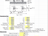
Cross-Sectional Geometry (Moment of Inertia, I): The moment of inertia (I) is a geometric property that describes a beam’s resistance to bending. For a rectangular section with a width (b) and depth (h), the moment of inertia about the neutral axis (the axis about which bending occurs) is calculated as:
I = (b * h³) / 12
This equation reveals the significant impact of the beam’s depth (h) on its bending stiffness. Doubling the depth increases the moment of inertia by a factor of eight, drastically reducing deflection. The width (b) has a linear relationship with the moment of inertia.
-
Support Conditions: The type of supports (e.g., simply supported, fixed, cantilever) significantly affects the deflected shape and the magnitude of maximum deflection. Different support conditions result in different bending moment diagrams, which directly influence deflection.
Calculating Deflection in Rectangular Beams:
The calculation of deflection typically involves using formulas derived from the principles of beam bending theory. These formulas relate the applied load, span, material properties, and cross-sectional geometry to the resulting deflection.
General deflection formulas often take the form:
δ = (Constant) * (Load * Span³) / (E * I)
The “Constant” in this equation depends on the specific loading configuration and support conditions. Here are some common examples for simply supported rectangular beams:
-
Simply Supported Beam with a Concentrated Load (P) at Mid-Span:
δ_max = (P * L³) / (48 * E * I) -
Simply Supported Beam with a Uniformly Distributed Load (w):
δ_max = (5 * w * L⁴) / (384 * E * I)
For other loading and support conditions, you can find appropriate deflection formulas in structural engineering textbooks and design codes.
Practical Considerations for Civil Engineers:
-
Serviceability Limit States: Deflection limits are typically specified in building codes as part of the serviceability limit states (SLS) to ensure the functional performance and appearance of structures. These limits are often expressed as a fraction of the span (e.g., L/240, L/360).
-
Material Properties: Accurate material properties (especially the modulus of elasticity) are crucial for reliable deflection calculations. These values are usually provided in material standards or obtained through testing.
-
Load Combinations: Deflection should be checked under appropriate service load combinations, considering sustained loads (dead loads) and variable loads (live loads). Creep and shrinkage in concrete members can also contribute to long-term deflections.
-
Software Tools: Modern structural analysis software can perform deflection calculations for complex beam configurations and loading scenarios, providing engineers with accurate and efficient results. However, understanding the underlying principles remains essential for interpreting these results and making informed design decisions.
-
Increasing Stiffness: If calculated deflections exceed allowable limits, engineers can increase the beam’s stiffness by:
-
Increasing the beam’s depth (most effective).
-
Increasing the beam’s width.
-
Using a material with a higher modulus of elasticity.
-
Reducing the beam’s span.
-
Modifying the support conditions.
-
Conclusion:
Understanding the factors that influence deflection in rectangular beam sections and the principles behind deflection calculations is fundamental for responsible civil engineering design. By carefully considering applied loads, span lengths, material properties, and cross-sectional geometry, engineers can design structures that meet serviceability requirements, ensuring their long-term performance, functionality, and aesthetic integrity. This knowledge, combined with the appropriate use of design codes and software tools, empowers civil engineers to create safe and serviceable structures for the benefit of society.