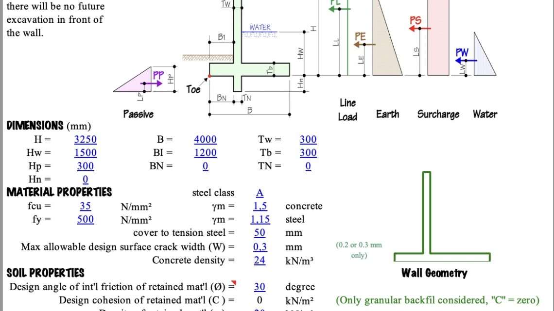
Retaining Wall Design to BS 8110 Spreadsheet
2 August 2025Table of Contents
Retaining Wall Design to BS 8110 Spreadsheet
Retaining walls are the unsung heroes of civil engineering, holding back tons of earth to create usable, level ground. But behind every successful wall is a meticulous design process. A failure to get this right can lead to catastrophic and costly consequences.
This guide provides a clear, step-by-step approach to designing a cantilever reinforced concrete retaining wall, grounded in the robust and widely-understood principles of BS 8110. Whether you’re a student, a graduate engineer, or a seasoned pro looking for a refresher, this is your blueprint for success.
The Three Pillars of Stability: The Core of Your Design
Before a single piece of rebar is calculated, your wall must prove it is stable as a whole. It must win three critical battles against the forces of nature. The design process always starts here.
1. The Battle Against Overturning (Tipping Over)
The most intuitive failure mode is the wall tipping over about its “toe” (the front edge of the base).
-
Destabilizing Force: The primary enemy is the horizontal pressure from the soil (lateral earth pressure) pushing against the vertical stem of the wall. This force creates a powerful overturning moment.
-
Stabilizing Force: Your ally is gravity. The sheer self-weight of the concrete wall and, crucially, the weight of the soil sitting on the “heel” (the back part of the base) work to hold the wall down. This creates a stabilizing moment.
The Golden Rule: The total stabilizing moments must be significantly greater than the overturning moments. A typical factor of safety required is 2.0. This means your wall’s ability to stay upright must be at least double the force trying to tip it over.
2. The Battle Against Sliding (Being Pushed Forward)
Next, you must ensure the wall doesn’t simply slide forward along its base.
-
Destabilizing Force: The enemy is the same—the total horizontal thrust from the retained earth.
-
Resisting Force: The resistance comes from the friction between the concrete base and the soil beneath it. This frictional force is a product of the total vertical weight of the wall and the soil on its heel.
The Golden Rule: The total resisting force must be greater than the sliding force. A typical factor of safety required is 1.5.
Pro-Tip: The Shear Key. If the sliding resistance is insufficient, a shear key—a small downward projection from the base—can be added. This dramatically increases resistance by engaging the passive strength of the soil in front of it.
3. The Battle Against Bearing Pressure (Sinking into the Ground)
Finally, the ground itself must be strong enough to support the immense weight of the wall and the soil it’s retaining.
The forces on the wall create a downward pressure on the soil beneath the base. This pressure is not uniform; it’s typically higher at the toe and lower at the heel.
-
You must calculate the maximum pressure under the toe and the minimum pressure under the heel.
-
The maximum pressure must not exceed the soil’s safe bearing capacity (a value determined from a geotechnical investigation).
-
Ideally, the entire base should remain in compression, meaning there should be no uplift or tension at the heel.
Only after your wall has passed these three stability checks with the required factors of safety can you proceed to the structural design of the concrete itself.
Structural Design: Reinforcing the Concrete with BS 8110
Now, we design the individual concrete components (stem, heel, and toe) as cantilever slabs, calculating the reinforcement needed to handle the internal stresses.
1. Designing the Stem (The Vertical Wall)
The stem acts as a vertical cantilever, fixed at the base and pushed by the lateral earth pressure.
-
Calculate Bending Moment: Determine the maximum bending moment at the junction of the stem and the base. This is your primary design moment.
-
Design Vertical Reinforcement: Using BS 8110 principles, calculate the area of vertical steel reinforcement required on the inner (earth) face of the wall to resist this bending moment.
-
Check for Shear: Verify that the concrete section is strong enough to resist the shear force at the base. While shear is rarely critical in tapered stems, it must always be checked.
2. Designing the Heel (The Rear Base Slab)
The heel acts as a cantilever, fixed at the back of the stem. It is loaded downwards by the massive weight of the soil sitting on top of it, but pushed upwards by the soil bearing pressure from below. The net effect is a force trying to bend the heel downwards.
-
Calculate Bending Moment: Determine the maximum bending moment at the back face of the stem.
-
Design Top Reinforcement: This bending action creates tension in the top of the slab. Therefore, you must provide reinforcement in the top of the heel to resist this force.
3. Designing the Toe (The Front Base Slab)
The toe also acts as a cantilever, fixed at the front of the stem. It is loaded almost exclusively by the upward-acting ground bearing pressure.
-
Calculate Bending Moment: Determine the maximum bending moment at the front face of the stem.
-
Design Bottom Reinforcement: This upward force creates tension in the bottom of the slab. Therefore, provide reinforcement in the bottom of the toe to counteract this.
Crucial Details for a Successful Design
-
Drainage is Everything: The calculations assume you are retaining drained soil. Water pressure (hydrostatic pressure) is immensely powerful and will lead to failure if not managed. Always include proper drainage behind the wall, such as weep holes and a granular backfill.
-
Surcharges: Be aware of any additional loads behind the wall, like slopes, roads, or building foundations. This “surcharge” adds significant pressure and must be included in your calculations.
-
Reinforcement Detailing: Pay close attention to concrete cover for durability, appropriate lap lengths for splicing bars, and correct bar spacing. These details are critical for turning a good design on paper into a durable structure on site.
By following this logical sequence—stability first, then element design—and adhering to the sound engineering principles of BS 8110, you can design retaining walls that are safe, efficient, and built to last.


