Beam on Elastic Foundation Analysis Sheet
14 March 2019Beam on Elastic Foundation Analysis Sheet
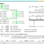
BOEF is a spreadsheet program written in MS-Excel for the purpose of analysis a finite length beam with free ends supported continuously on an elastic foundation. This program is ideally suited for analyzing a soil supported beam, a combined footing, or a strip of a slab or a mat. Specifically, the beam shear, moment, deflection, and soil bearing pressure are calculated for 100 equal beam segments, as well as the maximum values. Plots of both the shear, moment, and soil bearing pressure diagrams are produced, as well as a tabulation of the shear, moment, deflection, and bearing pressure for the beam.
Program Assumptions and Limitations:
1. The following reference was used in the development of this program (see below):
“Formulas for Stress and Strain” – Fifth Edition – by Raymond R. Roark and Warren C. Young, McGraw-Hill Book Company (1975), pages 128 to 146.
2. This program uses the equations for a “finite-length” beam in the analysis. This usually gives very similar to exact results for a “semi-infinite” beam which has had end-corrections applied to “force” the moment and shear values to be equal to zero at the ends. (Note: a “semi-infinite” beam is defined as one that has a b*L value > 6.)
3. This program uses the five (5) additional following assumptions as a basis for analysis:
- Beam must be of constant cross section (E and I are constant for entire length, L).
- Beam must have both ends “free”. (“Pinned” or “fixed” ends are not permitted.)
- Elastic support medium (soil) has a constant modulus of subgrade, K, along entire length of beam.
- Applied loads are located in the center of the width, B, of the beam and act along a centroidal line of the beam-soil contact area.
- Bearing pressure is linearly proportional to the deflection, and varies as a function of subgrade modulus, K.
4. This program can handle up to twelve (12) concentrated (point) loads, a full uniformly distributed load with up to six (6) additional full or partial uniformly distributed loads, and up to four (4) externally applied moments.
5. Beam self-weight is NOT automatically included in the program analysis, but may be accounted for as a full uniformly distributed applied load. Beam self-weight will only affect the deflection and bearing pressure, and not the moment or shear.
6. This program will calculate the maximum positive and negative shears, the maximum positive and negative moments, the maximum negative deflection, and the maximum soil bearing pressure. The calculated values for the maximum shears, maximum moments, deflection, and bearing pressure are determined from dividing the beam into 100 equal segments with 101 points, and including all of the point load and applied moment locations as well.
7. The user is given the ability to input four (4) specific locations from the left end of the beam to calculate the shear, moment, deflection, and bearing pressure.
8. The plots of the shear, moment, and bearing pressure diagrams as well as the displayed tabulation of shear, moment, deflection, and bearing pressure are based on the beam being divided up into 100 equal segments with 101 points.
9. This program contains numerous “comment boxes” which contain a wide variety of information including explanations of input or output items, equations used, data tables, etc. (Note: presence of a “comment box” is denoted by a “red triangle” in the upper right-hand corner of a cell. Merely move the mouse pointer to the desired cell to view the contents of that particular “comment box”.)
More from my site
 General Beam Analysis and Calculation Spreadsheet
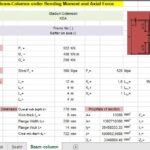
- Design Beam-Columns Under Bending Moment and Axial Force Spreadsheet
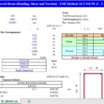
- Design Of Doubly Reinforced Beam According to ACI 318-99 Spreadsheet
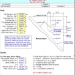
- Beam And Punching Shear Checks For Pile Cap Spreadsheet
- Beam Design Reinforcement middle and support span bars Spreadsheet
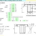
- Concrete Beam Design for New or Existing Based on ACI 318-14 Spreadsheet