ClipConnTable – Beam And Connections Using Clip Angles Spreadsheet
17 August 2019ClipConnTable – Beam And Connections Using Clip Angles Spreadsheet
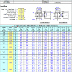
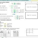
“ClipConnTable” is a spreadsheet program written in MS-Excel for the purpose of analysis of steel beam end connections using double clip angles either welded or bolted to the beam web, and bolted to either the column flange, column web, or girder web. The connections may be subjected to end shear reaction and/or axial load. Specifically, all applicable “limit states” for the end connection analysis pertaining to the clip angles, bolts, beam web, column flange or web, and girder web are checked. The program is presented in a “tabular” format.
This program is a workbook consisting of four (4) worksheets, described as follows:
Doc – documentation sheet
Conn Table (Welded Clips) – Clip angles welded to beam web and bolted to support
Conn Table (Bolted Clips) – Clip angles bolted to beam web and bolted to support
Conn Table (Welded or Bolted) – Clip angles either welded or bolted to beam web and bolted to support
Program Assumptions and Limitations:
1. The most critical assumption used in this program is that all beam end connections are basically “full-depth”, utilzing as many vertical rows of bolts as permitted. See first page of each worksheet for outline of other assumptions used.
2. This program is basically a “tabular” format version of the “CLIPCONN.xls” program, and is best suited to analyze a large number of beam end connections in a very quick, efficient, and concise manner. (Note: The individual case worksheets in the “CLIPCONN.xls” program were used as “masters calculations” in the development of this program, and may be referred to for individual detailed calculations.)
3. Once the user has inserted the required input data in cells starting at A408 through F408 and down for each of the connections to be analyzed, then the user should copy the row of cells from G62 through the end cell of the particular spreadsheet (either CI408, CV408, or EG408) and “Paste Special” the formulas on down the worksheet to match the total number of connections to be analyzed.
4. This program follows the procedures and guidelines of the AISC 9th Edition Allowable Stress (ASD) Manual (1989) and the AISC 9th Edition Manual Vol. II – Connections (1992).
5. This program uses the database of member dimensions and section properties from the “AISC Shapes Database”, Version 3.0 (2001) as well as the AISC 9th Edition (ASD) Manual (1989).
6. This program assumes that the tension capacity for any “limit state” is reduced by the presence of shear. For allowable bolt tension in the presence of shear, the “interaction” (combined stresses) is handled directly by the AISC Code equations. For other “limit states” in combined stresses such as bolt bearing, gross and net shear and tension, and block shear and tension tearout, the effect of “interaction” is handled by use of the formula, P/Ra+(R/Rv)^2=1, as suggested from the following reference:
“Combined Shear and Tension Stress” – by Subhash C. Goel, AISC Journal, 3rd Qtr.-1986.
Thus, the reduction factor applied to the tension “limit state” capacity is = (1-R/Rv)^2.
where:R = actual shear end reaction; Rv = allowable shear capacity for the particular “limit state” considered
7. This program contains numerous “comment boxes” which contain a wide variety of information including explanations of input or output items, equations used, data tables, etc. (Note: presence of a “comment box” is denoted by a “red triangle” in the upper right-hand corner of a cell. Merely move the mouse pointer to the desired cell to view the contents of that particular “comment box”.)
Calculation Reference
AISC