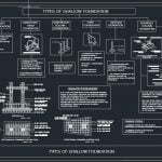
The principal types of foundations
29 July 2019Table of Contents
The principal types of foundations
Isolated Footings
Footings are understood formed by a rigid rectangular base of stone or concrete of dimensions : width B and length L, in which the ratio of L/B will not exceed 1.5.
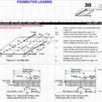
The foundation structure will support the column load. The bearing capacity of the footing may be stimated, and its dimensions selected ; thereafter, a forcast of the settlement is made.
To illustrate the case pf footing foundations, consider a building with nine columns (Fig 1) supported on isolated footings. In this case, the footings will work independently of each other. Therefore, it is required that the differential settlements between footings will not exceed the allowable total and differential settlement requirements.
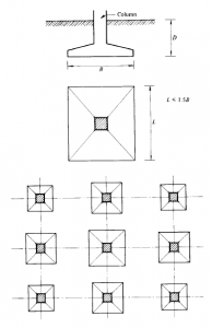
Figure 1: Isolated Footings
The differential settlements may be reduced selecting properly the area of the footings, and at times, using the stiffness of the superstructure.
From the structural point of view, however, the superstructure should not be allowed to take high secondary stresses induced bu the differential settlements of the footinhs, except in very special casees.
Singles footing foundations, in general, will be user only in soils of low compressibility and in structures where the differential settlements between columns may be controlled by the superstructure flexibility, or including in the design og the building joints or hinges that will take the differential settlements and/or rotations, respectively, without damaging the construction.
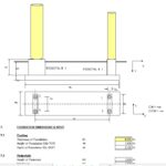
Continuous Footings
When it is necessary to control within certain limits the magnitude of differential settlements between columns supported on footings, and when soil deposits of medium or low compressibility atre encountered, it is recommended to use continuous footings. They may be defined as resisting elements joining columns together by foundation beams.
Continious footings are arraged by joining two or more columns together with beams.
The vertical differential displacements may be controlled via beam stiffness (Fig 2). The selection of the foundation beams, either running in one direction or the other along columns rows, depends largely on the layout of the column loads, and othe functional requirements concerning the structural and architectural design of the project.
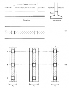
Figure 2: Continuous Footings
For heavier loads, and when the project calls foor stiffness in both directions (namely, along column rows A, B and C also rows 1,2 and 3), the foundations is given stiffness with beams in both directions (Fig 3).
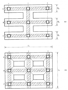
Figure 3: Continuous Footings
In this case, it may be observed that the footing slabs will cover practically all the foundation. This type of foundation using continuous footings is advantageous in soils of medium compressibility, where it is necessary to control differential movements between colomns.
The foundation beams are designed with the necessary stiffness to fulfill the differential settlements requirements.
Raft Foundation
When the loads are so largee that continious footings will occupy close to 50% of projected area of the building, it is more economical to use a continuous mat covering the entire area, as shown in Fig 4. The total load in this case may be assumed uniformly distributed in the area covered by the building.
The soil reaction is determined on the basis of a safe bearing capacity. The total and differential settlements may be investigated considering the stiffness of tthe raft or foundation slab is a matter of economy, compatible with the allowable differential settlements.
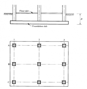
Figure .4 : Mat Foundations
Flexibility is important to obtain economy ; however, restrictions in differential vertical displacements between colmuns may call for certain slab stiffness, either by making it thicker or by placing foundation beams joining columns rows.
The beams can be designed with the required stiffness to reduce differential displacements.
This type of foundation may be used generally in soil deposits of medium compressibility ; however, in certain instances, the surface raft foundation may be used in soils of high and very high compressibility, where large total settlements may be allowed.
This type of foundation may be used efficiently in reduucing differential settlement.
Compensated Foundations
In soil deposits of medium, high and very high compressibility and low bearing capacity, compensated foundations are indicated.
This type of foundation requires a monolithic box foundation, as shown in Fig 5. When the water table is close to the ground surface, water proofing is necessary to use the buoyancy effect in designing the foundation.
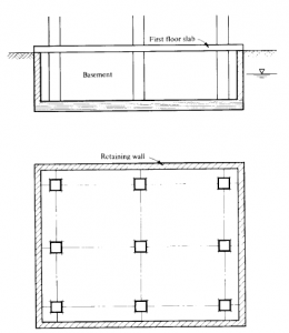
Figure .5 : Compensated Foundation
In the design of compensated foundations, it should be borne in mind that the soil should be consedered as a material of two phases, namely : a solid and liquid phase.
Therefore, in a compensated foundation, the compensation is made by adding two effects :
- Substitution of the submerged weight of solids.
- The buoyancy effect by weight of liquid displaced.
Both effects are used to equalize the total weight of the building. The volume of the concrete box forming the foundation strructure annd basements will displace a weight of liquid that, according to Archimedes’ principal, will contribute in floating the foundation up to this value, reducing the load applied to the solid phase.
The load taken by the solid phase will, however, deform the soil because of the change in effective stresses induced in the soil structure. It shoul be investigated from the point of view of bearing capacity of the soil and total and differentioal settlements, as previously discussed for other foundations.
Compensated Foundations with Friction Piles
When a compensated foundation as described is not sufficient to support the load with the allowable total settlement, in spite of desigin the foundation with sufficient stiffness to avoid detrimental differential settlements within the foundation itself, friction piles may be used in addition to the concept of compensation.
This case may be present in deposits of high or very high compressibility extending to great depth. The piles will reinforce the upper part of the soil where a higher comopressibility is encountered.
The applicability of this foundation calls for a soil that varies from very high compressibility at the upper part of the deposit, to medium or low compressibility at the bottom (Fig 6).
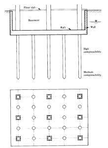
Figure 6: Compensated friction pile Foundation
Point Bearing Pile Foundations
When the loads to be supported are higher than those a compensated friction pile foindation can take, the nit will be required to find a deep-seated hard stratum of low to very low compressibility and high shear strenth, where piles can be driven to point bearing. One can distinguish two cases of point bearing foundations (Fig 7 and Fig 8).
The first case is recognized when the hard stratum of convenient thickness is found underlain by materials of medium compressibility. In these cases the piles should be evenly distributed as shown in Fig 7. After solving the problem of point bearing of the piles in the hard stratum, there still existas the problem of finding if the lower compressible soil stratum will have a safe bearing value, and also if the total and differential settlements will be within the allowable values specified for the foundation in question.
This type of foundation should be designed with sufficient stiffness to control differential settlements.
The second type of pile fooundation is recognized wwhen the point bearing piles rest in a firm deposit of low compressibility extending to great despth (Fig 8). In this case, it is economical to use groups of piles to solve the foundation problem.
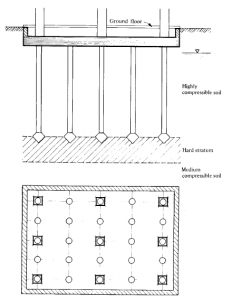
Figure 7 : Point Bearing Piles
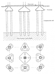
Figure 8 : Point Bearing Piles in groups
The columns will rest on single footings supported on the piles. The piles driven in the firm stratum develop laterad friction contributing to the mechanical properties on shear strengh of the depostigs in whttich the are driven, on the spacing of the piles, on the length of penetration into the bearing stratum, and on the state of density and confinement of such stratum.
Pier Foundations
Pier foundations are used to support very heavy loads in buried soil deposits of very low compressibility (Fir 9). Their load capacity is a function of the mechanical properties of the soil under the base of the pier, and of the confining stress of the bearing stratum. Actuelly, the bearing capacity of such an element is determined as a deep-seated isolated footing.
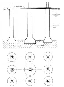
Figure 9 : Pier Foundation
The piers, columns-like elements cast in place, in most cases carry high loads of 500 ton or moore ; therefore, the compressibility of the deposit on which the are resting should be very low, in order that they may be recommended.
Pier shafts may be used from dimensiosn are also a function of the procedure used to perform the excavation, and of the way the hydraulic conditions are handled. The density of the material wherre these elements aare bearing may be altered during excavations if an upward water flow is produced. Specially important is the case when the material is a cohesionless fine sediment or when the cohesion is small, in which case it is necessary to perform the excavation using a pneumatic system, introducing air under sufficient high pressure to balance the flow of water toward the bottom of the excavation, preserving the natural confining and density connditions of the bearing stratum.
Usually, if precautions are taken in the installation of these elements, the settlements will be very small. The settlement, however, may be estimated knowing the stress-strain characterictics of the strata encouontered under the base of the piers. The nagative friction on these elements may take large proportions : hence, it shoul be estimated.
When these rigid elements are used in seismic regions to support loads through deposits of high and very high compressibility, it is necessary to investigate the effect ot the horizontal motion of the soil mass during earthquakes. The horizontal drift forces against the piears because of soil displacement should not be overlooked. In occasions, rigid elements have been damaged because of the strong horizontal motions produced bu the earthquakes.
Sand Pier Foundations
The solution of foundations using sand pier or sand piles is shown in Fig 10.
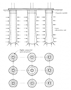
Figure 10 : Sand Piers
This type of foundation is used to increase the load capacity of the soil by reducing its compressibility and increasing its shear strength capacity properties. This type of pile may be used in loose or medium dense sand deposits.
The improvement of the subsoil is a function of the volume of sand introduced at the time thses elements are installed. Usually first a hole is driven in the ground, then sand is introduced and highly compacted in layers, using a heavy ram.
The sand element will take the load because of the lateral confinement given by the subsoil. The deformation of these elements may be estimated by means of the stress-strain properties of the sand ussed, considering the pier as a long sand cylinder laterally confined bu the soil. This type of foundation is only recommended in places where the cost of cement is very high, and good aggregates to fabricate concrete are difficult to obtain.
More from my site
 Types of Shallow Foundation Autocad Drawing
- Backfilling in Foundation: Types and Procedures
- The Best Collection Of Civil Engineering Spreadsheets
- The Best Collection Of Reinforcement Concrete Autocad DWG Drawings
- Spreadsheet For Combined Foundation Design With Piles
- Trapezoidal Soil Loading Foundation Calculation Spreadsheet