Design implication for corrosion behaviour
10 May 2020Table of Contents
Design implication for corrosion behaviour
The design of a plant has significant implications for its subsequent corrosion behaviour. Good design minimizes corrosion risks whereas bad design promotes or exacer- bates corrosion.
1. Shape
The shape of a vessel determines how well it drains (Figure 1). If the outlet is not at the very lowest point process liquid may be left inside. This will concentrate by evaporation unless cleaned out, and it will probably become more corrosive.
This also applies to horizontal pipe runs and steam or cooling coils attached to vessels. Steam heating coils that do not drain adequately collect condensate. This is very often contaminated by chloride ions, which are soon concentrated to high enough levels (10-100 ppm) to pose serious pitting and stress corrosion cracking risks for 300-series austenitic stainless steel vessels and steam coils.
Flat-bottomed storage tanks tend to suffer pitting corrosion beneath deposits or sediments which settle out. Storage tanks may be emptied infrequently and may not experience sufficient agitation or flow to remove such deposits.
Flange face areas experience stagnant conditions. Additionally, some gasket materials, such as asbestos fibre, contain leachable chloride ions.
This creates crevice and stress corrosion cracking problems on sealing surfaces. Where necessary, flange faces which are at risk can be overlaid with nickel-based alloys. Alternatively, compressed asbestos fibre gaskets shrouded in PTFE may be used.
Graphite gaskets can cause crevice corrosion of stainless steel flanges. Bends and tee-pieces in pipework often create locally turbulent flow. This enhances the corrosivity of the process liquid. These effects should be minimized by the use of flow straighteners, swept tees and gentle bends.
Flow- induced corrosion downstream of control valves, orifice plates, etc. is sometimes so serious that pipework requires lining with resistant material for some twelve pipe diameters beyond the valve.
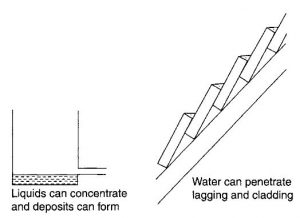
Fig.1. Details of design creating corrosion problems
2. Stress
The presence of tensile stress in a metal surface ren- ders that surface more susceptible to many kinds of corrosion than the same material in a non-stressed condition.
Similarly, the presence of compressive stress in the surface layer can be beneficial for corrosion, and especially stress corrosion cracking, behaviour.
Tensile stresses can be residual, from a forming or welding operation, or operational from heating-cooling, filling-emptying or pressurizing-depressurizing cycles. The presence of a tensile stress from whatever origin places some materials at risk from stress corrosion cracking.
Some items of plant can be stress-relieved by suitable heat treatment, but this cannot prevent operational stress arising. Cyclic stresses can also give rise to fatigue or corrosion fatigue problems.
Information relating to the fatigue life of the material in the service environment is required, together with the anticipated number of stress cycles to be experienced by the item over its operational life. The fatigue life (the number of cycles to failure) or the fatigue strength (the stress level below which it does not exhibit fatigue problems) is then used in the design.
The presence of stress raisers, including sharp comers and imperfect welds, produces locally high stress levels. These should be avoided where possible or taken into account when designing the materials for use in environments in which they are susceptible to stress corrosion cracking or corrosion fatigue.
3. Fabrication techniques
Most fabricational techniques have implications for corrosion performance. Riveted and folded seam construction creates crevices as shown in Figure 2.
Those materials which are susceptible to crevice corrosion should be fabricated using alternative techniques (e.g. welding). Care should be taken to avoid lack of penetration or lack of fusion, since these are sites for crevice corrosion to initiate.
Welding should be continuous, employing fillets where possible, since tack welds create locally high stresses and leave crevice sites. Welding consumables should be chosen to create weld metals of similar corrosion resistance to the parent material.
This often requires the use of a slightly over-alloyed consumable, to allow for loss of volatile alloying elements during the welding process and to compensate for the inherently poorer corrosion resistance of the weld metal structure.
Strongly over-alloyed weld consumables can create galvanic corrosion problems if the weld metal is significantly more noble than the parent material.
In all welds the heat-affected zone is at risk. The new structure which forms as a consequence of the thermal cycle can be of lower corrosion resistance, in addition to the often poorer mechanical properties, than parent material.
Austenitic steels such as type 304 and 316 are also susceptible to sensitization effects in the heat-affected zone. In these materials carbide precipitation during the welding thermal cycle denudes the parent material of chromium.
This creates areas of significantly diminished corrosion resistance, resulting in knife-line attack in many corrosive environments. This is avoided by the use of the low-carbon equivalents (304L, 316L, etc.) or grades such as type 321 or 347 which are stabilized against sensitization.
With correct welding techniques, however, this should be necessary only with thick sections (5 mm for 304 and 8 mm for 316). Some materials, particularly certain aluminium alloys, duplex stainless steels in certain reducing environments and most steel plate, are susceptible to end-grain attack.
Penetration along the end grain can be very rapid, with corrosion exploiting the potential differences that exist between inclusions and ferrite crystals in steel and between austenitic and ferrite grains in duplex stainless steel.
Where end-grain attack is significant this should not be exposed to the corrosive environment. It can be covered by a fillet ‘buttering’ weld if necessary.
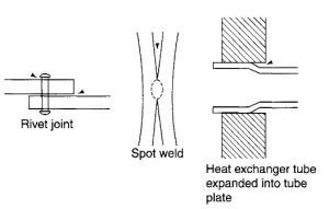
Fig.2. Details of jointing processes creating additional corrosion risks (crevices and stress concentrations)
4. Design for inspection
Unseen corrosion can be the most damaging type of attack. Items should be designed to permit periodic inspection.
This involves the provision of sufficiently large manways, the installation of inspection pits, the placing of fiat-bottomed vessels on beams instead of directly onto concrete bases and the facility for removal of thermal insulation from vessel walls.