Permeability of Soil: Definition, Darcy’s Law and Tests
14 December 2018Permeability of Soil: Definition, Darcy’s Law and Tests
Definition of Permeability:
It is defined as the property of a porous material which permits the passage or seepage of water (or other fluids) through its interconnecting voids.
A material having continuous voids is called permeable. Gravels are highly permeable while stiff clay is the least permeable, and hence such a clay may be termed impermeable for all practical purpose.
The study of seepage of water through soil is important for the following engineering problems:
1. Determination of rate of settlement of a saturated compressible soil layer.
2. Calculation of seepage through the body of earth dams and stability of slopes for highways.
3. Calculation of uplift pressure under hydraulic structure and their safety against piping.
4. Groundwater flow towards well and drainage of soil.
Darcy’s Law (1856) of Permeability:
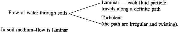
For laminar flow conditions in a saturated soil, the rate of the discharge per unit time is proportional to the hydraulic gradient.
q = kiA
v = q/A = Ki … (7.1)
Where q = discharge per unit time
A = total cross-sectional area of soil mass, perpendicular to the direction of flow
i = hydraulic gradient
k = Darcy’s coefficient of permeability
v = velocity of flow or average discharge velocity
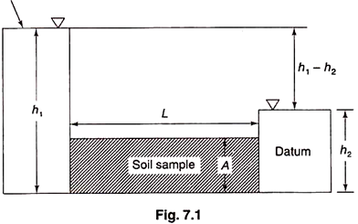
If a soil sample of length L and cross-sectional area A, is subjected to differential head of water h1 – h2, the hydraulic gradient i will be equal to [(h1 – h2)/L] and we have q = k. [(h1 – h2)/L].A.
When hydraulic gradient is unity, k is equal to V. Thus, the coefficient of permeability, or simply permeability is defined as the average velocity of flow that will occur through the total cross-sectional area of soil under unit hydraulic gradient. Dimensions are same as of velocity, cm/sec.
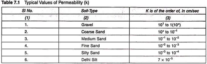
The coefficient of permeability depends on the particle size and various other factors. Some typical values of coefficient of permeability of different soils are given in Table 7.1.
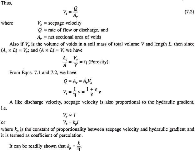
Discharge Velocity and Seepage Velocity:
The total cross-sectional area of the soil mass is composed of sectional area of solids and voids, and since flow cannot occur through the sectional areas of solids, the velocity of flow is merely an imaginary or superficial velocity.
The true and actual velocity with which water percolates through a soil is called the velocity of percolation or seepage velocity. It is the rate of discharge of percolating water per unit of net sectional area of voids perpendicular to the direction of flow.
In accordance with the Darcy’s Law, the velocity of flow through soil mass is directly proportion to the hydraulic gradient for laminar flow condition only. It is expected that the flow to be always laminar in case of fine-grained soil deposits because of low permeability and hence low velocity of flow.
However, in case of sands and gravels flow will be laminar upto a certain value of velocity for each deposit and investigations have been carried out to find a limit for application of Darcy’s law.
According to researchers, flow through sands will be laminar and Darcy’s law is valid so long as Reynolds number expressed in the form is less than or equal to unity as shown below –
![]()
Where v = velocity of flow in cm/sec
Da = size of particles (average) in cm.
It is found that the limiting value of Reynolds number taken as 1 is very approximate as its actual value can have wide variation depending partly on the characteristic size of particles used in the equation.
Factors affecting permeability are:
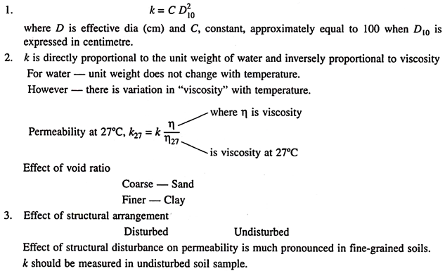
1. Grain size
2. Properties of pore fluid
3. Void ratio of the soil
4. Structural arrangement of the soil particle
5. Entrapped air and foreign matter
6. Adsorbed water in clayey soil
4. Effect of degree of saturation and other foreign matter
k will decrease if air is entrapped in the voids thus reducing its degree of saturation. Percolating water in the field may have some gas content, it may appear more realistic to use the actual field water for testing in the laboratory.
Organic foreign matter also has tendency to move towards critical flow channels and choke them up, thus decreasing permeability.
5. Effect of adsorbed water – The adsorbed water surrounding the fine soil particle is not free to move, and reduces the effective pore space available for the passage of water.
Capillarity-Permeability Test:
The set-up for the test essentially consists of a transparent tube about 40 mm in diameter and 0.35 m to 0.5 m long in which dry soil sample is placed at desired density and water is allowed to flow from one end under a constant head, and the other end is exposed to atmosphere through air vent.
At any time interval t, after the commencement of the test, Let the capillary water travel through a distance x, from point P to Q. At point P, there is a pressure deficiency (i.e., a negative head) equal to hc of water.
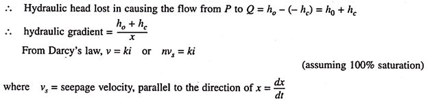
If the coefficient of permeability is designated as ku at a partial saturation S, the above expression can be rewritten as –
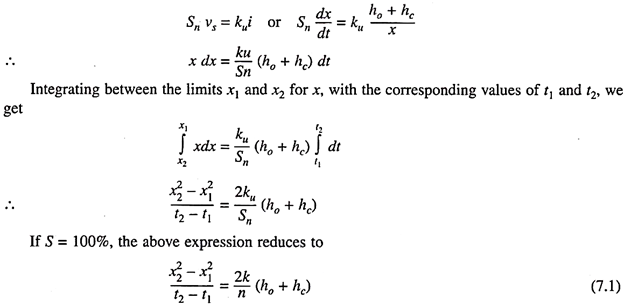
In order to find the two unknowns k and hc in the above equation, the first set of observations are taken under a head h1. As the capillary saturation progresses the values of x are recorded at different time intervals t.
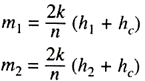
The values of x2 are plotted against corresponding time intervals t to obtain a straight line whose slope, say m, gives the value of [(x22 – x21)/(t2 – t1)] . The second set of observation are taken under an increased head h2 and values of x2 plotted against corresponding values of t to obtain another straight line, whose slope m2 will give the value [(x22 – x21)/(t2 – t1)].
By substitution in Eqn. 7.1, we obtain the following two equations, which are solved simultaneously to get k and hc.
The porosity n required in the above equation is computed from the known dry weight of soil, its volume and specific gravity of soil particles.
Permeability of Stratified Soil Deposits:
In general, natural soil deposits are stratified. Each layer may be homogeneous and isotropic. When we consider flow through the entire deposit the average permeability of deposit will vary with the direction of flow relative to the bedding plane. The average permeability for flow in horizontal and vertical directions can be readily computed.
Average Permeability Parallel to Bedding Plane:
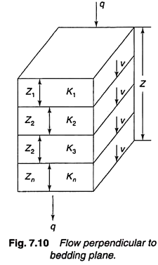
Figure 7.9 shows several layers of soil with horizontal stratification. Let Z1, Z2, ….Zn be the thickness of layers with permeabilities k1, k2, … kn.
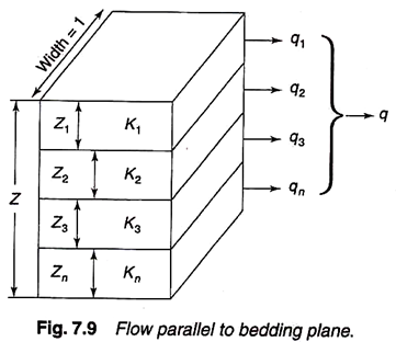
For flow parallel to bedding plane the hydraulic gradient i will be same for all layers. The total discharge through the deposit will be the sum of discharges through individual layers.
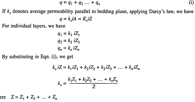
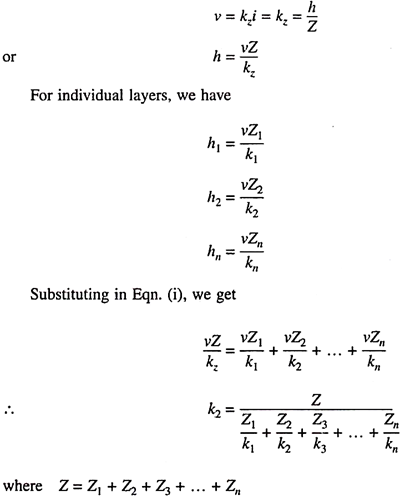
Average Permeability Perpendicular to Bedding Plane:
For flow in the vertical direction for the soil layers shown in Fig. 7.10.
In this case the velocity of flow, v will be same for all layers the total head loss will be sum of head losses in individual layers.
h = h1 + h2 + h3 + … + hn (i)
If kz denotes average permeability perpendicular to bedding plane, applying Darcy’s law, we have –