SHRINKAGE AND CREEP EFFECTS ON BRIDGE DESIGN
12 June 2019Table of Contents
SHRINKAGE AND CREEP EFFECTS ON BRIDGE DESIGN
SHRINKAGE:
Shrinkage cracks in concrete occur when excess water evaporates out of the hardened concrete, reducing the volume of the concrete.
CREEP:
Deformation of structure under sustained load. It’s a time dependent phenomenon. This deformation usually occurs in the direction the force is being applied. Like a concrete column getting more compressed, or a beam bending.
Creep does not necessarily cause concrete to fail or break apart. Creep is factored in when concrete structures are designed.
SHRINKAGE EFFECTS:
- The shrinkage of the prestressed beam is different from the shrinkage of the deck slab.
- This is due to the difference in age beam and slab therefore the differential shrinkage induce stresses in prestress composite beams.
- Larger shrinkage of deck causes composite beams to sag.
DIFFERENTIAL SHRINKAGE :
- Differential shrinkage between Slab and PS Beams creates internal stresses. It is assumed that half the total shrinkage of the beam has taken before the slab is cast.
- The effect of differential shrinkage will be reduce by creep. Allowance is made for this in the calculation by using creep coefficient φ.
- Φ (creep coefficient)= 0.43. Refer BS 8110 Clause 7.4.3.4
- DIFFERENTIAL SHRINKAGE STRAIN:
έDS= 0.5 x (-300×10-6)
Refer BS 8110 Clause 7.4.3.4 Table 29
- RESTRAINING FORCE:
RF = έDS x Ec x A(slab) x φ
- RESTRAINING MOMENT:
RM = RF x eccentricity
Eccentricity = y top of composite section – half of slab thicknes
- CALCULATION OF INTERNAL STRESSES
Restrained Stress (RS) = έDS x Ec x Ф
Axial Release (AR) = RF / X-sec area
Moment Release (MR) = RM x y / inertia
(for top and bottom stresses)
- NET STRESSES:
- TOP STRESSES:
Σ(RS , AR , MR)
- BOTTOM STRESSES:
Σ(MR , AR)
CREEP EFFECTS:
- We know creep are deformation under the sustained load as in case of prestressed beams prestressing load is applied at the bottom cause the deformation in upward direction and due to creep effect as time passes through long term deflections in upward direction is increases.
- For camber calculation longterm deflection factors
Dead = 2.0, SDL = 2.3, Prestressing = 2.2
- This increase in upward direction of simple span beam is not accompanied by stress in beam since there is no rotational restraint of the beam ends.
- When simple span beam are made continuous through connection at intermediate support, the rotation at the end of the beam tend the creep to induce the stresses.
More from my site
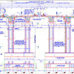
 Standard Pier View Autocad Free Drawing
- Geogrid Bridge Calculation Spreadsheet
- Exploring the Danyang–Kunshan Grand Bridge in China
- Innovative Bridge Design Handbook – Conctruction Rehabilitation and Maintenance Free PDF
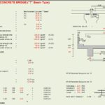
- Design Of Concrete Bridge T Beam Type Spreadsheet
- What is a truss Bridge ? Types of Bridge Trusses