Steel Beam and Column Analysis Spreadsheet
3 October 2021Steel Beam and Column Analysis Spreadsheet
This spreadsheet is a program written in MS-Excel for the purpose of analysis and code checking of steel beams and columns. Specifically, beams and columns are analyzed / code checked per the AISC 9th Edition Allowable Stress Design (ASD) Manual. Both actual and allowable stresses are computed, with the final result being a computed “stress ratio” of actual stress/allowable stress. Also, a list of the lightest weight members which satisfy the code check is displayed for convenience.
This program is a workbook consisting of six (6) worksheets, described as follows:
- Doc – Documentation sheet
- BeamCol(I) – Analysis / Code Check for W, S, M, and HP Shapes
- BeamCol(Built-Up) – Analysis / Code Check for Non-Database and Built-Up Shapes
- BeamCol(C) – Analysis / Code Check for Channel Shapes
- BeamCol(Tube) – Analysis / Code Check for Rectangular HSS (Tube) Shapes
- BeamCol(Pipe) – Analysis / Code Check for Round HSS and Pipe Shapes
All the worksheets are independent and self contained, so that you can move them from one workbook to another. All the worksheets are protected, but not with a password.
Program Assumptions and Limitations:
1. This program follows the procedures and guidelines of the AISC 9th Edition Allowable Stress (ASD) Manual (1989).
2. This program uses the database of member dimensions and section properties from the “AISC Shapes Database”, Version 3.0 (2001) as well as the AISC 9th Edition (ASD) Manual (1989).
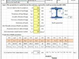
3. The “BeamCol(Built-Up)” worksheet is valid for AISC W, S, M, and HP shapes NOT contained in the AISC 9th Edition Manual, as well as for non-hybird and doubly-symmetrical (“I” shaped) built-up members which have their flanges continuously welded to the web and which DO NOT quailify as plate girders.(Note: the AISC Code limiting value on the web for built-up beams not to qualify as plate girders is as follows:
(d-2*tf)/tw <= 760/SQRT(0.60*Fy)
4. This program is NOT valid for tees (WT shapes) and angles.
5. In this program for members subjected to known loadings consisting of axial load (compression or tension) and/or uniaxial or biaxial bending, both the actual and allowable stress are computed, with the final result being a computed “stress ratio” of actual stress/allowable stress.
6. The “BeamCol(Built-Up)” worksheet will require the input for the total depth, web thickness, flange width, and flange thickness. Then, all the remaining section properties are automatically calculated, assuming straight,non-sloping flanges.
7. This program utilizes an “Allowable Stress Increase Factor” (ASIF) which is a multiplier of any of the calculated allowable stresses Fa, Fbx, and Fby and also the Euler column buckling stresses F’ex and F’ey. It is used and appears ONLY in the stress ratio calculation. Typically a value of 1.0 may be used. However, a value of 1.333 may be used for load combinations which include wind or seismic loads.
8. If an axially loaded compression member has a value of the maximum slenderness ratio K*L*12/r >200, then a message will appear. However, this program DOES NOT consider or deem a particular member as “inadequate” based on the slenderness ratio of 200 being exceeded.
9. For the case of combined axial compression with bending, if the calculated value of fa >=F’e (which is not allowed) then a warning (error!) message will appear.
10. When the values of either ‘Lx’, ‘Ly’, or ‘Lb’ are input = 0′ (or actually <= 1.0′), this program will use a value = 1.0′.
11. When a stiffened element (web) of a member subjected to axial compression is classified as a “slender” element (exceeding non-compact limits) based on local buckling criteria, then the program complies with AISC Appendix B.
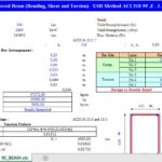
12. In the “BeamCol(C)” worksheet for channels subjected to Y-axis bending, the properties database uses the minimum value of ‘Sy’. However, it is desired to calculate the bending stress at the back of the channel instead of at the tips of the flanges, this may be done by computing a “reduced effective” Y-axis bending moment, Mye = My*Sy*(xbar)/Iy , for member loading input.
13. The values of ‘Cb’, ‘Cmx’, ‘Cmy’, ‘Kx, and ‘Ky’ may be calculated (if applicable) by accessing the additional input data to the right of the main page in each of the calculation worksheets. Then, these calculated values can be input under the member design parameters on the main page. (Note: there are equations which very closely approximate the solutions for ‘Kx’ and ‘Ky’ obtained using the AISC Code Alignment Charts.)
14. This program does not calculate or check shear or deflection in member
15. This program does not consider torsion on member.
16. This program does not consider deduction for holes in members subjected to tension.
17. This program contains numerous “comment boxes” which contain a wide variety of information including explanations of input or output items, equations used, data tables, etc. (Note: presence of a “comment box” is denoted by a “red triangle” in the upper right-hand corner of a cell. Merely move the mouse pointer to the desired cell to view the contents of that particular “comment box”.)
Calculation Reference
AISC
More from my site
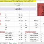
 Design Beam-Columns Under Bending Moment and Axial Force Spreadsheet
- Design and Calculation Of Steel Beam Spreadsheet
- Beam Calculator according to Structural Steel Building 2005 Spreadsheet
- General Beam Analysis and Calculation Spreadsheet
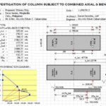
- Investigation Of Column Subject To Combined Axial and Bending Spreadsheet
- Design Of Doubly Reinforced Beam According to ACI 318-99 Spreadsheet