PRESENTATION ON DESIGN OF HILL ROAD ALIGNMENT
28 November 2018Table of Contents
PRESENTATION ON DESIGN OF HILL ROAD ALIGNMENT
Contents
- Hill Road Definition
- Design Issues in Hill Roads
- Special Consideration in Hill Road Design
- Route Selection
- Engineering Data for Design
- Geometric Design Standards
1. Hill Road Definition
A hill road may be defined as the one which passes through a terrain with a cross slope of 25% or more. There may be sections along hill roads with the cross slope less than 25%, especially when the road follows a river route. Even then these sections are also referred to as hill roads. Hence, to establish a hill road overall terrain must be taken into account.
The hilly regions generally have extremes of climatic conditions, difficult and hazardous terrains, topography and vast high altitude areas. The region is sparsely populated and basic infrastructural facilities available in plain terrain are absent. Hence, a strong stable and feasible road must be present in hilly areas for overall development of other sectors as well.
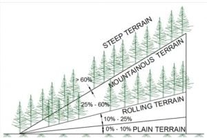
IRC:SP:73-2015 and IRC:SP:84-2014 have merged the Mountainous and Steep Terrain having Cross Slope more than 25%.

2. Design Issues in Hill Roads
Design and Construction of Hill roads are more complex than in plain terrain due to factors summarized below:
- Highly broken relief with vastly differing elevations and steep slopes, deep gorges etc. which increases road length.
- The geological condition varies from place to place.
- Variation in hydro-geological conditions.
- Variation in the climatic condition such as the change in temperature due to altitude difference, pressure variation, precipitation increases at greater height etc.
- High-speed runoff due to the presence of steep cross slopes.
- Filling may overload the weak soil underneath which may trigger new slides.
- Need of design of hairpin bends to attain heights.
- Need to save Commercial and Residential establishments close to the road.
- Need to save the ecology of the hills.
3. Special Consideration in Hill Road Design
a – Alignment of Hill Roads
The designer should attempt to choose a short, easy, economical and safe comforting route.
b – General considerations
- When designing hill roads the route is located along valleys, hill sides and if required over mountain passes.
- Due to complex topography, the length of the route is more.
- In locating the alignment special consideration should be made in respect to the variations in:
- Temperature
- Rainfall
- Atmospheric pressure and winds
- Geological conditions
- Resettlement and Rehabilitation considerations
- Environment Considerations
c – Temperature
- Air temperature in the hills is lower than in the valley. The temperature drop being approximately 0.5° per 100 m of rising.
- On slopes facing south and southwest snow disappears rapidly and rain water evaporates quickly while on slopes facing north and northeast rain water or snow may remain for the longer time.
- Unequal warming of slopes, sharp temperature variations and erosion by water are the causes of slope failure facing south and southwest.
d – Rainfall
- Rainfall generally increases with increase in height from sea level.
- The maximum rainfall is in the zone of intensive cloud formation at 1500-2500 m above sea level. Generally, the increase of rainfall for every 100 m of elevation averages 40 to 60 mm.
- In summer very heavy storms/cloud burst may occur in the hills and about 15 to 25% of the annual rainfall may occur in a single rainfall. The effects of these types of rainfall are serious and should be considered in design.
e – Atmospheric pressure and winds
- Atmospheric pressure decreases with increase in elevation.
- At high altitudes, the wind velocities may reach up to 25-30 m/s and depth of frost penetration is also 1.5 to 2 m.
- Intensive weathering of rocks because of sharp temperature variations.
f – Geological conditions
- The inclination of folds may vary from horizontal to vertical stratification of rock. These folds often have faults. Limestone or sandstone folds may be interleaved with layers of clay which when wetted may cause fracturing along their surface. This may result in shear or slip fold.
- The degree of stability of hill slopes depends on types of rock, degree of strata inclination or dip, occurrence of clay seams, the hardness of the rocks and presence of ground water.
- When locating the route an engineer must study the details of geological conditions of that area and follow stable hill slopes where no ground water, landslides, and unstable folds occur.
g – Resettlement and Rehabilitation
Due to limited availability of flat areas and connectivity issues, most of the residential and commercial activity happens very close to the road leading to large scale R&R and becomes a challenge in alignment design.
h – Environment
Hills are ecologically sensitive areas relatively untouched by human activity. The alignment design must attempt to minimize tree cutting and large scale earth filling/cutting to minimize damage.
4. Route Selection
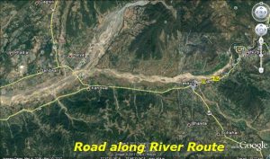
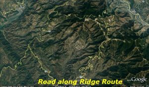
Hill road alignment may follow alignment at Valley bottom or on a ridge depending on the feasibility of the road. The first is called River route and the second is called Ridge route.
a – River route
- Most frequent case of hill alignment as there is a great advantage of running a road at a gentle gradient.
- Runs through lesser horizontal curvature.
- Requirements for the construction of bridges over tributaries.
- Construction of special retaining structures and protection walls on hill side for safe guarding the road against avalanches in high altitude areas.
- Benefit of low construction cost and operation cost.
b – Ridge route
- Characterized by the very steep gradient.
- Large number of sharp curves occurs on the road with hair pin bends.
- Extensive earthwork is required.
- The requirement for the construction of special structures.
- High construction and operation cost.
5. Engineering Data for Design
The design data includes:
The terrain classification all along the alignment – to be established through topographic data/ Contours of the area using Satellite Imagery.
All features like river course, streams, cross-drainage structures (for existing alignment), flooding areas, high flood levels, landslide areas, snow/avalanche prone areas etc.
River Morphology and Regime data.
Chainage wise inventory of the side slope material type i.e. soil with classification and properties, rock type and its structural geology of the area.
Hydrological data for all stream and river crossings.
Available material and resources that can be used in the road construction.
Geometric standards.
6 – Geometric Design Standards
a – Hill Road Capacity
| Type of Road | Design Service Volume in PCU per day | |||
| As per IRC:SP:48-1998 and IRC:52- 2001 |
As per IRC:SP:73-2015 & IRC:SP:84-2014 | |||
| For Low Curvature (0-200 degrees per km) |
For High Curvature (above 0-200 degrees per km) |
Level of Service ‘B’ | Level of Service ‘C’ | |
| Single lane | 1,600 | 1,400 | – | – |
| Intermediate lane | 5,200 | 4,500 | – | – |
| Two Lane | 7,000 | 5,000 | 9,000 | – |
| Four Lane | – | – | 20,000 | 30,000 |
b – Design Speed:
The design speed for various categories of hill roads are given below:
| Road Classification | As per IRC:SP:48-1998 and IRC:52- 2001 | As per IRC:SP:73-2015 & IRC:SP:84-2014 | ||||
| Mountainous Terrain | Steep Terrain | Mountainous and Steep Terrain | ||||
| Ruling | Minimum | Ruling | Minimum | Ruling | Minimum | |
| National and State Highways | 50 | 40 | 40 | 30 | 60 | 40 |
| Major District Roads | 40 | 30 | 30 | 20 | – | – |
| Other District Roads | 30 | 25 | 25 | 20 | – | – |
| Village Roads | 25 | 20 | 25 | 20 | – | – |
c – Sight Distance:
Visibility is an important requirement for safety on roads.
It is necessary that sight distance of sufficient length is available to permit drivers enough time and distance to stop their vehicles to avoid accidents.
| Design Speed (Km/h) | As per IRC:SP:48-1998 and IRC:52- 2001 | As per IRC:SP:73-2015 & IRC:SP:84-2014 | ||
| Mountainous and Steep Terrain | ||||
| Stopping Sight Distance (m) | Intermediate Sight Distance (m) | Safe Stopping Sight Distance (m) | Desirable Minimum Sight Distance (m) | |
| 20 | 20 | 40 | – | – |
| 25 | 25 | 50 | – | – |
| 30 | 30 | 60 | – | – |
| 35 | 40 | 80 | – | – |
| 40 | 45 | 90 | 45 | 90 |
| 50 | 60 | 120 | 60 | 120 |
| 60 | – | – | 90 | 180 |
d – Minimum Radius of Horizontal curves
|
Classification
|
As per IRC:SP:48-1998 and IRC:52- 2001 | As per IRC:SP:73-2015 & IRC:SP:84-2014 | ||||||||
| Mountainous terrain | Steep terrain | Mountainous and Steep | ||||||||
| Area not affected by snow | Snow Bound Areas | Area not affected by snow | Snow Bound Areas | |||||||
| Ruling Minimum | Absolute Minimum | Ruling Minimum | Absolute Minimum | Ruling Minimum | Absolute Minimum | Ruling Minimum | Absolute Minimum | Desirable Minimum Radius | Absolute Minimum Radius | |
| National Highway and State Highways | 80 | 50 | 90 | 60 | 50 | 30 | 60 | 33 | 150 | 75 |
| Major District Roads | 50 | 30 | 60 | 33 | 30 | 14 | 33 | 15 | – | – |
| Other District Roads | 30 | 20 | 33 | 23 | 20 | 14 | 23 | 15 | – | – |
| Village Roads | 20 | 14 | 23 | 15 | 20 | 14 | 23 | 15 | – | – |
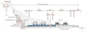
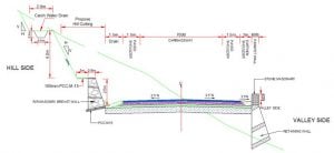
e – Typical Cross-sections – 2 lane carriageway (as per IRC:SP:73-2015)
f – As per IRC:SP:48-1998 and IRC:52- 2001
| Road Classification | Carriageway Width (m) | Shoulder Width (m) |
| National and State Highways | ||
| i) Single lane | 3.75 | 2 x 1.25 |
| ii) Double Lane | 7.00 | 2 x 0.9 |
| Major District Roads and Other District Roads | 3.75 | 2 x 0.5 |
| Village Roads | 3.00 | 2 x 0.5 |
i –Typical Cross-sections – 4 Lane Carriageway Widening Towards Valley Side (as per IRC:SP:84-2014)
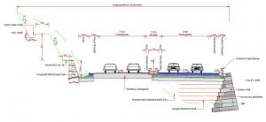
j –Typical Cross-sections – 4 Lane Carriageway Widening Towards Hill Side (as per IRC:SP:84-2014)