Prestressed Concrete Applications
1 August 2019Table of Contents
Prestressed Concrete Applications
Prestressed concrete is adaptable to a wide variety of structural systems. These include pretensioned and post-tensioned structures, both cast-in-place and precast, and other prestressed elements in conjunction with normally reinforced concrete.
While there is no general classification for precast and prestressed concrete, it is useful to group certain elements and structures together to explain how prestressed and precast concrete is designed and constructed.
Prestressed and precast concrete may be considered in four broad categories:
- Standardized Elements
- Fixed Cross Section Elements
- Fully Engineered Elements
- Precast Nonprestressed Elements
While there is some overlap, each group has its own unique characteristics.
The role of the engineer varies with the type and complexity of the structural system being constructed. Indeed, multiple engineers may be involved in some aspect of the design, fabrication, and construction of the project. In general, the design engineer who is typically the licensed design professional or engineer of record is responsible for the overall design.
The unique characteristics of prestressed concrete often require the additional services of a specialty engineer. The specialty engineers can either provide consulting services to or be employed by a precast plant or contractor. Specialty engineers can also be associated with post-tensioning companies either as an employee or consultant.
In either case, the specialty engineer takes the concept prepared by the licensed design professional and prepares final detailed design calculations as well as developing fabrication or construction details necessary to complete the project.
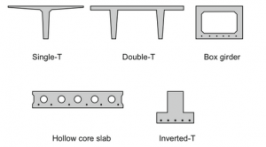
Figure 1 : Typical standardized sections
Standardized Precast Prestressed Elements
Pretensioned concrete beams and slabs are typically constructed in reusable steel forms in a precast plant. Although a modest amount of custom formwork is used at precast plants, improved quality and reduced costs are realized only when standardized elements are used.
They consist of standard sections such as single-T and double-T beams, box girders, hollowcore slabs, inverted T-beams, and bridgegirders (Fig. 1). The capital investment required to construct and equip a precast plant includes the concrete mixing equipment, forms, stressing beds, curing systems, and heavy lifting equipment.
To obtain a return on this investment, the forms and stressing facilities must be in constant use. Efficiencies in production allow the precast pieces to be fabricated on a routine and daily basis.
The cost efficiencies of this type of fabrication allow architects and engineers to select the sections for a wide number of uses and be sure of availability and competitive cost. Hollowcore planks, single-T, and double-T beams are used for as floor elements in building construction, Figs. 2 and 3. Inverted-T beams support double-T and hollowcore elements.
These elements are commonly used in combination in office space, bridges, and parking garages, Fig. 4.
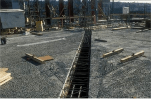
Figure 2 : Single-T floor beam before topping and cast-in-place beam
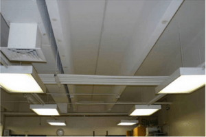
Figure 3 : Double-T floor element with suspended ceiling removed
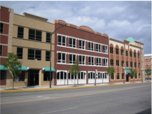
Figure 4 : Precast concrete panel for parking garage
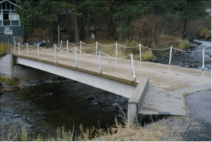
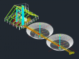
Figure 5 : Precast concrete double-T specialty bridge
Standardized elements are creatively incorporated in building structures. For example, entire buildings have been constructed of double-T sections as is discussed in the commercial building case study. Double-T beams and box girders are used for short-span low-volume bridge girders.
For example, following the flood in the Big Thompson Canyon in Colorado, double-T bridges were installed to replace the original structures, Fig. 5. The double-T bridges allowed a standard design to be developed and installed in multiple locations in the canyon. This solution accelerated the reconstruction effort.
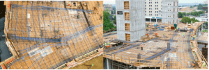
Figure 6 : Flat plate system with banded tendons
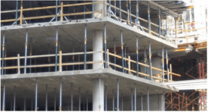
Figure 7 : Flat plate system with banded tendons
Engineer’s Role Standardized elements
The design engineer typically selects one of these standardized elements from references such as the PCI Design Handbook (2017) or the Manual for the Design of Hollow Core Sections (1998).
The design engineer may also contact precast plants located near the project to determine availability of sections.
The section type and the design loads are provided to the precast plant. Final detailed design engineering is completed by the precast plant or their specialty engineer in the form of shop drawings.
This process allows the design engineer the efficiency of selecting desired shapes for their function and allows the plant to select the appropriate number of strands, strand configurations, harping locations, and other details to maximize the performance of the plant operations to meet the project objectives.
Fixed Cross Section Elements
The design engineer is required to determine the prestressing forces and tendon locations in fixed cross section situations. Two common fixed section design conditions are post-tensioned beams and slabs for building or parking garage construction, and girders for bridge construction.
Other applications of fixed section elements include structures such as water tanks and post-tensioned slabs on-ground.
Flat plate and flat slab floor systems are ideally suited for the use of post-tensioning tendons, Figs. 6 and 7. Another popular system is one-way slab and beam floor systems that are cast-in-place, Figs. 8, 9, 10, and 11. The design engineer specifies a tendon profile geometry and an average effective post-tensioning force necessary to satisfy the design requirements.
The specialty engineer for the post-tensioning company then takes this requirement and produces a detailed design with tendon sizes and spacing along with anchorage and splice locations.
Pour strips and other detailing requirements necessary to isolate the post-tensioned element from other elements in the structure should be detailed by the engineer.
Selection of the tendon location is determined by the thickness of the slab. The maximum tendon eccentricity available to the engineer is determined by minimumcover requirements for corrosion and fire protection over the top and bottom of the tendon.
Therefore, in these applications, the section shape does not vary, but rather the design is controlled by the selection of the prestressed force and tendon spacing.
Another popular fixed section are two-way slab systems used as podium slabs.
Podium slabs are typically a single-story post-tensioned concrete floor system supported by columns that support a lighter superstructure above, which is usually wood or metal stud walls with a light floor system. These are popular for use in residential construction where the upper stories serve as the living areas and the area below the podium slab serves as parking. The podium slab is usually designed as a separate structure from that of the wood or metal stud superstructures. The individual structures may have two separate structural engineers.
Spliced bridge girders are an example of design to a fixed section using partially standardized precast, pretensioned elements that are also post-tensioned during the final stage of assembly, Fig. 12. State departments of transportation and AASHTO specify standard beam sections.
Precast plants have forms for bridge girder sections used in their market area. The section selection is dependent on the state practice and is further influenced by the distance that the girders are shipped. The variation and the magnitude of loads, load placement on the bridge, the girder spacing in the bridge, and the bridge deck design, preclude defining standard prestressing tendon forces and locations.
The design engineer selects from several choices regarding the layout and loading of the bridge prior to design of the prestressing force and location. Unlike standardized products, the design engineer specifies all details of the bridge girder.
Another example of spliced segmented precast construction using standardized shapes involves the use of plant-produced horizontally curved, precast concrete U-girders (Hamilton & Dolan, 2016). These U-girders use standardized shapes andgeometry along with post-tensioning to facilitate design and construction efficiency.
One example of this approach is shown in Fig. 13. Walls and tanks are a condition where the tendon location and force are determined within a fixed rectangular section, Fig. 14.

Figure 8 : One-way beam and slab system showing tendon passing through column at the top of the section and coiled slab tended ready to be placed

Figure 9 : One-way beam and slab system. Bundled tendons are seen at the beam bottom. Single slab tendons are on top of beam
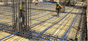
Figure 10 : One-way slab and beam floor system. Slab tendons placed parallel with the slab span
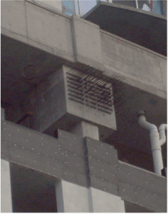
Figure 11 : One-way beam end anchorage detail
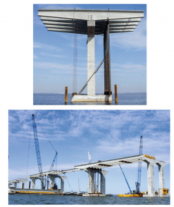
Figure 12 : Spliced girder bridge
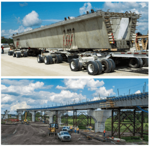
Figure 13 : Boggy Creek Road interchange at State Road 417 and Orlando International Airport’s

Figure 14 : Liquified Natural Gas tank showing circumferential post-tensioning tendons to ensure tank wall integrity under cryogenic conditions

Figure 15 : Parkland Hospital, Dallas, Texas. Seven stories are supported by girders with 62-ft cantilevers and 120-ft spans over an opening
Engineer’s Role with fixed section elements
The engineer’s role with fixed cross section element structures varies with the client and project. Some examples include:
- Building design engineers specify the desired final prestress force. The contractor or post-tensioning company specialty engineer completes the design by determining the tendon spacing and stressing forces. The design engineer thenapproves the contractor’s shop drawing submittal.
- Building design engineers specify the final prestress force, tendon location, and hardware detailing. Post-tensioning company engineer develops the tendon layout, anchorage location, and stressing sequence.
- Bridge design engineers prepare the complete beam design, including detailed determination of prestress forces, tendon location, and construction sequence.
- Projects such as tanks are often procured on a design–build basis. The contractor and either the contractor’s in-house engineering staff or a consulting engineer prepares the design to meet project requirements and the contractor’s preferred construction practice.
Fully Engineered Elements
Fully engineered elements require detailed engineering continuously during design and construction. Examples of fully engineered structures include segmental bridges, specialty transit structures, tanks, towers, stadiums, floating facilities, and unusual building construction. Design of these structures requires considerable engineering effort and often includes on-site inspection.
The complexity of these structures necessitates the engineer have a fundamental understanding of structural
behavior, loads, prestressing effects, and material behavior. Collaboration of efforts among engineers, precast plants, and general contractors is required.
Engineer’s role in fully engineered elements
Fully engineered elements require the engineer to define the loads, structural system, concrete section, prestressing
force, tendon location, and details (Figs. 15, 16, 17, and 18).

Figure 16 : Construction of Ironton Russell Bridge over the Ohio River. Longitudinal and transverse post-tensioning was used in the deck, which was cast-in-place using a form traveler.
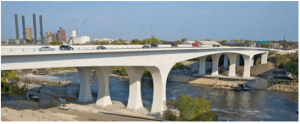
Figure 17 : St. Anthony Falls Bridge over the Mississippi in Minneapolis.
Each bridge has a main span of 154 m that consists of precast concrete box girder segments supported by eight 21 m high piers. The end spans are 108 m longeach cast-in-place, post-tensioned concrete box girders built on false work which seamlessly blends into the precast main span sections
Precast Nonprestressed Elements
The major difference in grouping is that pretensioned elements require significant plant capitalization and stressing beds. Precast pieces can be fabricated on the jobsite or in a facility without stressing beds and other equipment associated with a plant operation. Tilt-up walls are an example of on-site precasting.
If a small amount of prestressing is required for delivery, erection or final loads, it is provided in the form of single-strand post-tensioned tendons.
Two examples of precast nonprestressed elements are architectural precast panels and tilt-up construction. Architectural precast panels can be used either as structural elements or the exterior finish of buildings, Figs. 1, 4, and 6.
The architectural panel finish can include color, texture, or simulated alternative materials such as a brick or stone (Fig. 19). Dyes or colorants are used in these special concrete mixtures.
The architectural surfaces are made in small quantities and placed only on the outermost one to 1–1/2 in. of the precast piece. The backing concrete would be normal concrete to reduce costs. Textures are fabricated by sandblasting, retardants that are power washed off, Fig. 19, or liners in the form to develop more complex surface features like Fig. 20.
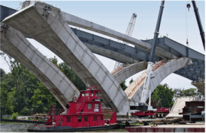
Figure 18 : Woodrow Wilson Bridge replacement across the Potomac River near Washington, DC

Figure 19 : Architectural wall panel finishing

Figure 20 : Architectural panel finish simulating sandstone rock
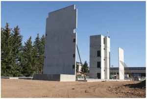
Figure 21 : Tilt-up wall panel construction
Tilt-up construction is a specialized form of precast construction where wall elements are fabricated on-site in a horizontal position. The floor of the structure is cast first. Edge forms are then laid out on the floor and the floor surface becomes the bottom of the wall form.
The wall elements, complete with block-outs for windows and electrical or mechanical inserts, are then cast and allowed to cure in-situ.
After the concrete has cured, the entire wall panel is lifted into a vertical position (ACI 551.2R, 2015). The tilt-up panel is temporarily braced against wind loads, Fig. 21.
Connections between wall elements and roof elements provide stability. The roof diaphragm carries lateral loads to the end panels, which act as shear walls.
Tilt-up construction is commonly used for commercial structures such as warehouses, and industrial facilities. While some architectural finish is possible, the most economical tilt-up construction uses a plain or painted concrete finish. Tilt-up elements require two design considerations in addition to the design for vertical and lateral loads.
These conditions are determination of the lifting positions and associated lifting hardware and the temporary bracing systems. The temporary bracing prevents damage under wind loads and is designed for a 6 month return period rather than the full 50 or 100-year return period (ACI 551.1R, 2014; Shah, 1995).
Engineer’s Role Precast concrete
The design engineer is typically responsible for all design elements in precast pieces. The specialty engineer is responsible for the lifting details and temporary bracing as part of the construction effort.
More from my site
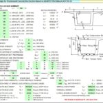
 Bridge Design For Prestressed Concrete Box Section Spreadsheet
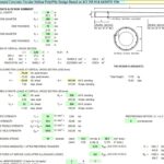
- Prestressed Concrete Circular Hollow Pole/Pile Design Based on ACI 318-14 & AASHTO 17th
- Dam at Brazil Mine Could Burst Soon, Officials Warn
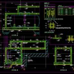
- Oil Tank Sections Details Autocad Free File
- Bentley PowerCivil for Middle East V8i (SELECTseries 4)
- Existing Column Enhancement Spreadsheet