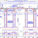
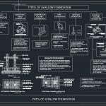
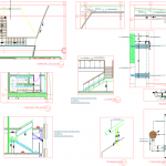
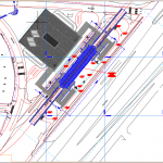
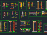
Table of Contents
Retaining Wall Details Free Drawing
Retaining wall details drawing is an important process in civil engineering and construction planning. It involves creating accurate technical drawings that show the structural components, dimensions, reinforcement, and drainage systems of retaining walls. These drawings are essential for ensuring stability, safety, and long-term performance.
What Is Retaining Wall Details Drawing?
Retaining wall details free drawing refers to manually or digitally drafting the structural details of a retaining wall without relying entirely on pre-made templates. Engineers and designers create these drawings to clearly illustrate how the wall will resist soil pressure and environmental loads.
These drawings are commonly prepared using:
-
AutoCAD or other CAD software
-
Structural drafting tools
-
Hand-drawn technical sketches for conceptual planning
Importance of Retaining Wall Detail Drawings
Accurate retaining wall drawings are crucial for preventing structural failure. A poorly designed wall can lead to soil collapse, water buildup, or foundation damage.
Key benefits include:
-
Improved structural stability
-
Proper load distribution
-
Effective drainage planning
-
Compliance with building codes and standards
Detailed drawings ensure that contractors understand reinforcement placement, footing size, and backfill requirements.
Essential Components in Retaining Wall Drawings
When creating retaining wall details free drawings, include the following key elements:
1. Wall Stem
The vertical portion that holds back the soil. The thickness and reinforcement must be clearly specified.
2. Base Slab (Footing)
The foundation that supports the wall. It includes:
-
Heel (under the backfill)
-
Toe (front portion of the base)
Dimensions and reinforcement bars should be accurately labeled.
3. Reinforcement Details
Show the size, spacing, and placement of steel bars (rebar). Indicate bar bending schedules if required.
4. Drainage System
Proper drainage prevents hydrostatic pressure buildup. Include:
-
Weep holes
-
Drainage pipes
-
Gravel backfill layers
-
Filter fabric
5. Backfill and Soil Information
Specify soil type, compaction requirements, and slope details.
6. Section and Elevation Views
Provide cross-sections and side elevations to clearly show structural components.
Best Practices for Retaining Wall Free Drawing
To ensure professional and accurate drawings:
-
Follow structural design codes and geotechnical recommendations
-
Maintain proper scaling and dimensioning
-
Clearly label all materials and specifications
-
Use consistent line weights for clarity
-
Double-check reinforcement placement and footing dimensions
Using digital drafting tools improves precision and efficiency.
Applications in Construction and Infrastructure
Retaining wall detail drawings are used in:
-
Residential landscaping projects
-
Highway and bridge construction
-
Basement and foundation systems
-
Slope stabilization projects
-
Commercial site development
Engineers rely on these detailed drawings to guide construction and ensure safety.
Conclusion
Retaining wall details free drawing is a fundamental part of structural and geotechnical design. Accurate technical drawings help prevent failure, improve durability, and ensure compliance with construction standards. Whether created by hand or using CAD software, detailed retaining wall drawings play a critical role in successful infrastructure projects.
To download more Free Autocad Templates visit www.cadtemplates.org


