The Benefits Of Machine Control and GPS
5 June 2021The Benefits Of Machine Control and GPS
What Is GPS and How Does It Work?
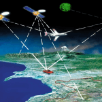
GPS is a product of the Cold War. Developed by the US military during the President Reagan years, this system consists of a series of 24 satellites in geosynchronous orbit. That is, these satellites remain in the same fixed location in the sky. Out of 360 degrees of longitude, each satellite covers a 15-degree sweep of the globe. They orbit the earth twice each day, broadcasting a timing signal. These signals can be intercepted by ground antennae mounted on ships, tanks, planes—or the buckets and blades of heavy earthmoving equipment.
Though, like all broadcast signals travelling at the speed of light, there is a small-but-measurable time lag between the signals from adjacent satellites. The difference, measured in milliseconds, allows for the triangulation between the ground antennae and the satellites emitting the signal. This triangulation measurement allows for the measurement of the precise location (measured in latitude, longitude, and elevation above sea level) on the surface of the earth where the receiving antennae is currently located. As is true so often in the history of technology, a technical advancement meant for use in war has been modified and adopted for peaceful civilian applications. A system intended to track the movements of men, weapons, ships, and war planes is now used to follow the movements of commercial shipments, find lost hikers, and guide construction equipment.
GPS guides equipment operations through their Automated Positioning Report System (APRS). Using triangulation between the several of the system’s broadcasting satellites allows for positional measurements with accuracies up to 30 centimeters (1 foot). The use of APRS increases this accuracy to 1 centimeter when used in conjunction with GPS. What APRS does is integrate GPS with the equipment’s controls. An APRS replaces the manually operated hydraulic drive cylinders traditionally used to control the movements of an excavator’s arm or dozer’s blade with electronically controlled servo-type valves. These servos send an electric current that creates magnetic field that rotate suspended armatures, that are further connected to fixed flapper arms. These flapper arms provide the linkage to the rotary spools that increase and decrease hydraulic pressure to the hydraulic systems. These are part of the closed-loop hydraulic system that controls the direction, flow rate, and applied pressure of the hydraulic fluid.
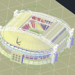
Going from individual pieces to equipment to an entire fleet of equipment or trucks is also easily managed by GPS applications. This allows a fleet owner to coordinate and choreograph the movements and activities of an entire fleet of earthmoving equipment and also track the locations of trucks delivering material to the site or hauling dirt away for disposal. Like pieces on a chessboard (or, more accurately, objects in a video game) these activities are tied to an onsite digital terrain model (DTM) of the project site.
This is a three-dimensional (3D) model created by an AutoCAD program, which utilizes a patchwork of connected triangles. The corners of each triangle is defined mathematically by three special coordinates (northing, easting, and elevation). While not a perfect match (no model ever is) to the actual terrain, this geometric surface comes the closes to matching actual surfaces. This is especially true for post construction or excavation surfaces, which tend to be regular and smooth.
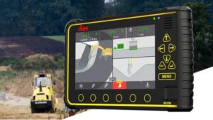
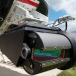
Leica excavator machine control solution
The software interacts with the model and the equipment hardware via sensors attached to the business end of the machine (the edge of the dozer blade, the teeth of an excavator bucket, etc.). These sensors continuously record and update the movements of the equipment using the same 3D location system as the DTM. The sensors relay their current location back through the system to the operating controls, which in turn direct the movement of the equipment in accordance with the programmed DTM for the proposed construction surface or excavation grades.
Coordinating all of the mobile GPS sensors on each piece of equipment is a stationary GPS sensor combined with an antenna with a receiver called the base station that is set up adjacent to the operating area. The base station is permanently located over a pre-surveyed reference point, such as a third order benchmark that has been established by ground survey. If necessary, some relative location (manhole rims, street curbs, and building corners, etc.) whose elevation is not exactly known but can be treated as a local datum for the project area can also be utilized for ground antennae setup.
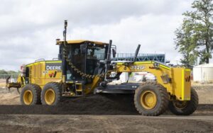
Grader GPS Control
The hardware for these control signals consists of a control box connected to the servo valves via electrical cable, which, in turn, connects to the hydraulic control system that physically moves the equipment. It is the incoming satellite data from the GPS system that tells the equipment where it is. The DTM design files are stored in a compact-flash memory card, memory stick, or accessed externally from data broadcast by the site’s controlled area network (CAN). The database, CAN, and GPS operate in real time to place a blade or bucket exactly where it needs to go and move it so that it accomplishes its task with the need for rework or wasted effort. All three elements, mobile sensors, base sensors, and equipment operator are in continuous communication with each other. The blades and buckets simultaneously move back and forth, up, and down in combination to achieve the desired movement.
Where and When Is GPS Best Used?
The advantages of using GPS guidance systems are legion. Using advanced systems, an operator can increase productivity by greater than 50% compared to purely manual operations. The increase in productivity comes indirectly by the avoidance of having to perform rework at the site. Guided by GPS, an equipment operator can get his cuts and placements right the first time. Furthermore, material wastage is minimized. GPS doesn’t necessarily increase the number of productive hours per day so much as it makes every hour a machine is active much more productive.
This has all sorts of secondary benefits and cost savings. Getting the most out his earthmoving equipment allows a contractor to get the most out of his workforce as well. This reduces labor costs, another costs savings, while reducing the impact of local labor shortages—always an issue in a booming economy with a considerable amount of construction activity. Furthermore, grades and elevations can be checked in real time as the work is being performed. The operator can check his elevation from within his cab as he is working. There is no more need to stop work at regular intervals and have a manual survey performed of the work zone to check its accuracy. In the past, the accuracy-checking task has traditionally relied on a crewmember inside the trenches to manually check depths and slopes. Now with these systems, the need for that task is greatly reduced—thereby cutting job site costs and improving crew safety. This traditional cause of equipment downtime is mostly avoided with the use of GPS.
Giving operators the tools to perform accuracy checks also gives greater responsibility, initiative, and job satisfaction. The additional training that the operators receive has the effect of empowering them, increasing senses of purpose and self-worth. This alone has a marked, if indirect, impact on productivity. By eliminating rework and improving employee morale, any money spent training operators on GPS is a wise investment that pays for itself very quickly. Human factors also show improvement in the area of site safety. The precision guidance and ability to choreograph equipment movement across a busy site improves safety by maintaining safe work zones, avoiding known utility locations, preserving the foundations of existing structures, and maintaining a safe flow of traffic.
GPS systems are often augmented by laser guidance for precise finish work. Lasers can compensate for some of GPS limitations. GPS works best with an open sky and no significant overhead blockage. (For example, GPS is not used for tunneling operations.) Laser guidance stations and targets mounted on equipment blades can work in any outdoor situation, with or without overhead blockage from trees and tall buildings. GPS, however has a much greater effective operating range, limited only by the availability of open sky. Lasers systems are usually limited to about 1,500 feet. GPS can allow for the construction of complicated surface models as well as flat, sloping surfaces. Lasers, being line of site instruments, are usually limited to operations on long, flat, or sloping surfaces. (Though they, too, can build surfaces as directed by a 3D design model represented by a surface AutoCAD file.)
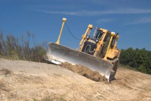
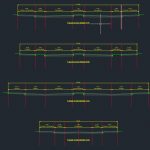
Grade Control System
Productivity can be measured in many ways: time savings, labor costs, material costs, fuel costs, quality bonuses, and finish bonuses. It begins as early as the job layout.
With Machine Control and GPS, you don’t have to wait for someone to stakeout the project or weather that permits someone to stakeout. This allows you to get started sooner. Any design change will also benefit as productivity increase due to not having to wait for restaking.
As the operator starts moving material you will see great value in being able to move the correct amount of material, to the correct location, the first time. This, along with only using the exact amount of material, will translate into a productivity savings.
You can also use GPS by having job layouts of the site so the machines or supervisors’ tablets can have the precise storage locations of materials, job trailers, or site boundaries. This can help having the right things in the correct location or, better yet, not in the way, therefore reducing excessive handling of material.