Asphalt paver, how it works?
22 March 2019Table of Contents
Asphalt paver, how it works?
A paver (paver finisher, asphalt finisher, paving machine) is a piece of construction equipment used to lay asphalt on roads, bridges, parking lots and other such places. It lays the asphalt flat and provides minor compaction before it is compacted by a roller.
All machines consist of two basic units; the tractor unit and the screed unit.
1. Tractor Unit
1.1 General:
The tractor unit provides moving power for the paver wheels or tracks and for all powered machinery on the paver. The tractor unit includes the receiving hopper, feed conveyor, flow control gates, distributing augers (or spreading screws), power plant (engine), transmissions, dual controls, operator’s seat, and wheels or tracks.
When in operation, the tractor unit power plant (engine) propels the paver, pulls the screed (leveling) unit, and provides power to the other components through transmissions. Hot mix is deposited in the hopper from where it is carried by the feed conveyor through the flow control gates to the distributing augers (spreading screws).
The augers distribute the mix evenly across the full width of the paver for uniform placement onto the roadway surface. These operations are controlled by the paver operator by means of dual controls within easy reach of the operator’s seat. Refer to Figure 1. Many pavers have hydrostatic drive systems that permit an unlimited number of speeds within the operating range and once set, will automatically maintain the desired speed. 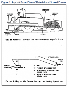
1.2 Pneumatic Tires and Crawler Tracks:
The tractor unit may be equipped with either rubber tires or steel tracks. If the paver is equipped with pneumatic tires, tire condition and air pressure must be checked. It is particularly important for the pressure to be the same in tires on both sides of the paver.
If the paver moves on tracks (crawlers), the tracks should be checked to be certain they are snug but not tight, and the drive sprockets should be checked for excessive wear. Low tire pressure or loose crawlers can cause unnecessary movement of the paver, which when transmitted to the screed unit results in an uneven pavement surface. There should be no build-up of material on tires or on tracks. Excessively worn parts should be replaced.
1.3 Governor :
The governor on the engine must be checked to be sure there is no periodic surge in the engine RPM. If it is not working properly, there can be a lag in power when the engine is loaded. Such a lag causes temporary failure of the vibrators or tamping bars in the screed unit, resulting in a stretch of pavement that is less dense or contains slightly less material than the immediately adjacent area. After rolling, such an area shows up as a transverse ripple in the pavement. A power lag can also interfere with the smooth and consistent operation of electronic screed controls.
1.4 Hopper, Flow Gates and Augers :
The hopper, the slats on the feed conveyor, the glow gates, and the augers should be checked for excessive wear and observed to be certain they are operating properly. Necessary adjustments should be made by the contractor to ensure these components are functioning as designed and are able to deliver a smooth flow of mixture from the hopper to the roadway.
All of the machines have adjustable flow control gates, which regulate the amount of the paving mixture, which is carried on the slat feeders from the receiving hopper to the distributing augers. The slat feeders should be operating most of the time (80% to 90%) and the flow control gates should be set to keep the augers at least two-thirds covered with material. It is very important that the level of the material in front of the screed be kept fairly constant.
If the level of material is allowed to intermittently rise and fall and thereby flood or starve the screed, a rough mat, segregation of the material, and imperfections in the surface will result. Some pavers are equipped with automatic controls to maintain a uniform depth of material ahead of the screed; the adjustment of the sensing device and the flow gates should be coordinated so the slat feeders operate most of the time as stated above.
Quarter-line cracking or raveling of the mat is believed to be caused by worn interior augers, paddles, and baffles that tend to starve the screed near the center of the paver. Such equipment should be regularly inspected, and if excessively worn, should be replaced or rebuilt to original dimensions.
Feeders, gates, and augers should be checked for excessive wear. They should be observed while operating without mixture to be assured they are functioning properly and in synchronism with each other.
2. Screed Unit
2.1 General:
The screed unit strikes off the mix, controls thickness, imparts smoothness, and provides initial compaction of the mixture. A typical screed unit is comprised of the following: screed tow arms, screed plate, hearing unit, tamping bars or vibratory attachments, and controls.
The screed unit is towed by long arms attached to pivot points located forward on the tractor unit, permitting the screed to operate on a floating principle which tends to compensate or dampen irregularities in the base that affect the tractor unit. Mat thickness is adjusted manually by tilting the screed up or down around a pivot pin just above the screed.
When operating an automatic grade control the screed compensates for irregularities in the base by adjusting the screed arm at or near the pivot point of the screed arms. As the manual thickness controls are adjusted, the screed seeks a new level, up or down, as the machine moves forward, but the total effect of the change may not be realized until the machine has moved several feet. Consequently, the machine should be allowed to move 50 feet before any further adjustments are made.
The sensitivity of the controls differs between makes of machines and consequently the maximum amount of adjustment that should be made at any time differs with the machine. The amount of change in thickness produced by any given adjustment on the controls depends on the mixture being placed, so it is impossible to state that a particular adjustment will change the mat thickness by a definite amount.
Refer to Figure 1. Screeds with tamping bars or vibratory mechanisms are designed to strike off and then compact the mixture slightly as it is placed. There are two purposes to this screed action. It achieves maximum leveling of the mat surface, and it ensures minimum distortion of the mat surface, and it ensures that minimum distortion of the mat surface will occur with subsequent rolling. Because the different screed compaction systems function differently, they are discussed separately below.
2.2 Tamping Bar Type:
Tamping bar type screed compactors compact the mix, strike off the excess thickness, and tuck the material under the screed plate for leveling. The tamper bar has two faces; a beveled face on the front that compacts the material as the screed is pulled forward and a horizontal face that imparts some compaction. The horizontal face primarily strikes off excess material so the screed can ride smoothly over the mat being laid.
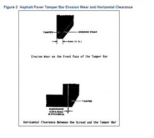
The adjustment that limits the range of downward travel of the tamping bar is the single most important adjustment affecting the appearance of the finished mat. At the bottom of its stroke, the horizontal face should extend 0.016″ – about the thickness of a fingernail – below the level of the screed plate. If the bar extends down too far, mix builds up on the screed face that tends to scuff the surface of the mix being placed.
In addition, the tamping bar will lift the screed lightly on each downward stroke, often causing a rippling of the mat surface. If the horizontal face of the tamping bar is adjusted too high (either by poor adjustment or due to wear of the bottom of the horizontal face), the bar does not strike off excess mix from the mat. Consequently, the screed plate begins to strike off the material, which results in surface pitting of the mix being placed as the leading edge of the screed plate drags the larger rocks forward.
Therefore, the tamper bar should always be checked before operating the paver. If necessary, the contractor should adjust it, and before it approaches knife-edge thinness it should be replaced. Refer to Figure 2. Clearance between the rear of the tamper bar and the leading edge of the screed frequently is overlooked.
Properly adjusted, there should be just enough clearance to allow free movement of the tampers – approximately 0.010″ to 0.020″. Refer to Figure 2. Screed plates will wear out first about 4″ to 6″ in from the trailing edge. The first indications will be either an indentation or an actual ripple in the surface of the screed plate. These should be checked periodically and replaced as needed.
2.3 Vibratory Type:
he operation of vibratory screeds is similar to that of tamping screeds, except that the compactive force is generated not by a tamping bar, but by either electric vibrators, rotating shafts with eccentric weights, or hydraulic motors that vibrate the screed plate.
On some pavers, both the frequency (number of vibrations per minute) and the amplitude (range of motion) of the vibrators can be adjusted. On others, the frequency remains constant and only the amplitude can be adjusted. Frequency and amplitude are set in accord with the type of pavers, speed of the paver, thickness of the mat, and the characteristics of the mixture. Once set, frequency and amplitude do not normally need adjustment until mat thickness or mixture change.
Some pavers have a “pre-strike-off unit” or a curved strike-off blade at the leading edge of the screed for use with “critical” material. It is attached to and receives vibration from the screed plate itself. It meters the amount of material going under the screed plate and can be adjusted vertically. Some other pavers have a round-nose strike-off bolted directly to the screed frames and welded to the screed plate so no adjustment can be made.
In these, the screed shield assembly is the only part of the screed that is adjustable. It can be moved up for normal material flow or down for dense mixes and thin lifts. As with tamping screeds, the screed plates will begin to wear first about 4″ to 6″ in from the trailing edge. Those with excessive wear should be replaced.
2.4 Oscillating Type:
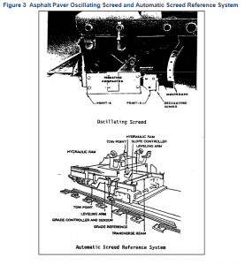
Some pavers are equipped with both an oscillating screed and a vibrating compactor. The oscillating screed, beveled for initial compaction, operates at 600 strokes per minute, with 1/4″ transverse strokes, striking off the material for the desired depth. The vibrating compactor, mounted to the rear of the oscillating screed, supports the screed unit, imparts additional compaction, and irons out the surface of the mat.
The most critical adjustment is positioning the oscillating screed relative to the vibrating compactor. The bottom rear edges of the oscillating screed and the bottom rear edges of the vibrating compactor must be parallel. The compactor should be sloped or tilted so that a projection of the plane of the bottom will intersect at a point 0.4″ above the bottom of the screed. Minor adjustments in this differential may be necessary to obtain a uniform appearance in the mat. Refer to Figure 3.
2.5 Crown Adjustment :
All machines have provision for adjustment of crown in the screed. Usually it is desirable to provide a slight amount of crown in the screed to avoid the appearance of the mat being low in the center of the lanes.
The usual crown allowed per lane on rural-type pavements is 0.10″; however, urban cross sections may require special adjustment. Also, the amount of crown at the front edge of the screed is generally increased somewhat from that required at the back, with at least a 0.08″ increase usually being recommended.
The amount of this differential may be varied with the particular material being used, and is sometimes helpful in reducing and eliminating non-uniformity of the surface texture across the paved width. Too much crown in the leading edge of the screed will crease an open texture along the edges. Too little crown in the leading edge will create an open texture down the center of the mat.
2.6 Automatic Screed Controls:
The paver shall be equipped with an approved automatic control system, which controls longitudinal grade and transfer slope, except when paving miscellaneous areas or when the engineer finds the use of this system impractical.
The specifications require the use of such longitudinal control, unless the engineer permits its omission on the final surface course. Exceptional conditions could arise, however, where omission of the longitudinal grade control in the interest of a smoother ride can be permitted.
The engineer may discontinue use of the automatic equipment and require manual control when it appears better results may be obtained thereby. Such might be the case on work which includes sections with an urban-type cross section with non-uniform crown, or on intersections, interchanges, or similar areas.
Pavers not equipped with automatic controls may be used when the engineer determines the use of such controls is impracticable, as on small specialized projects, jobs entirely urban with variable crown, or jobs having frequent intersections or other features which are not adaptable to such use.
When the automatic grade control fails, the paver can be operated under manual control for only the remainder of the working day on which the automatic control system broke down. The automatic control systems use electronic sensors to control grade and to control transverse slope. Refer to Figure 3. The sensor gets its information from a sensing device riding on a fixed stringline, a mobile stringline, or a traveling straightedge.
The specific type of sensing device used on the initial lane of a layer or course is subject to the engineer’s approval. For paving subsequent lanes of the course or layer, the paver may use a shoe or straightedge riding on the adjacent lane as a sensor.
There are several grade sensor types and transverse slope sensor types. Some systems make screed adjustments by raising or lowering the pull arm pivot points with hydraulic rams activated through solenoids. Some make adjustments by varying the angle of hinged pull arms through electrically driven screws. Others adjust the thickness control screws with electric servomotors.
In operation, once the screed is set for the desired depth of spread, the automatic system takes over to produce a smooth mat. Transverse slope is controlled by a pendulum that acts through switches to activate the appropriate piston. The sensitivity of the controls is critical to the smoothness of the mat. The sensors should be properly nulled as provided in the manufacturer’s instructions.
2.7 Heaters :
The screed assembly is equipped with heaters to prevent the mix from sticking to the screed plate. They are used to heat the screed plate at the start of paving operations or on a cool, windy day. Heaters should never be used to heat mix being delivered to the paver. Heaters should be observed while lit to assure they produce sufficient heat.
2.8 Screed Extensions:
Extensions should be attached properly to the main section of the screed. They should be, as their name implies, an extension of the plane of the tamper bar and the screed section if uniform compaction behind the paver is to be attained.
Pavers with a vibratory main screed and vibratory side extensions should be checked by the inspector for satisfactory frequency. Use of a vibrating reed tachometer held against the main screed unit and each extension will give quick, reliable, and measurable results to be compared against manufacturer’s authentic data.
The accuracy of variable vibratory frequency control supplied on some models could also be checked with the tachometer.
2.9 Maintenance :
An important item of paver operation, often overlooked, is proper clean up of the paver at the end of the working day. While the machine is still warm from its day’s operations, the hopper, feeder augers, tamper bars, and screed plates should all be cleaned and sprayed with a light oil to assure smooth start-up the next day of use.
More from my site
 Materials for pavement construction
- Flexible Pavement Design And Calculation According to AASHTO Spreadsheet
- Benefits of Using AI in Highway Design
- Highway Engineering – Pavement, Materials ans Control Of Quality Free PDF
- Testing and Characterization of Asphalt Materials and Pavement Structures Free PDF
- Pavement Management for Airports Roads and Parking Lots PDF