Classification of piles foundation
15 November 2019Table of Contents
Classification of piles foundation
Classification of pile with respect to load transmission and functional behaviour
- End bearing piles (point bearing piles)
- Friction piles (cohesion piles )
- Combination of friction and cohesion piles
End bearing piles
These piles transfer their load on to a firm stratum located at a considerable depth below the base of the structure and they derive most of their carrying capacity from the penetration resistance of the soil at the toe of the pile (see figure 1.1).
The pile behaves as an ordinary column and should be designed as such. Even in weak soil a pile will not fail by buckling and this effect need only be considered if part of the pile is unsupported, i.e. if it is in either air or water. Load is transmitted to the soil through friction or cohesion. But sometimes, the soil surrounding the pile may adhere to the surface of the pile and causes “Negative Skin Friction” on the pile.
This, sometimes have considerable effect on the capacity of the pile. Negative skin friction is caused by the drainage of the ground water and consolidation of the soil. The founding depth of the pile is influenced by the results of the site investigate on and soil test.
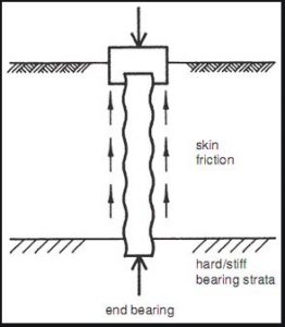
Fig.1.1 – End Bearing Piles
Friction or cohesion piles
Carrying capacity is derived mainly from the adhesion or friction of the soil in contact with the shaft of the pile (see fig 1.2).
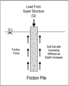
Fig.1.2 – Friction Pile
Cohesion piles
These piles transmit most of their load to the soil through skin friction. This process of driving such piles close to each other in groups greatly reduces the porosity and compressibility of the soil within and around the groups. Therefore piles of this category are some times called compaction piles.
During the process of driving the pile into the ground, the soil becomes moulded and, as a result loses some of its strength. Therefore the pile is not able to transfer the exact amount of load which it is intended to immediately after it has been driven. Usually, the soil regains some of its strength three to five months after it has been driven.
Friction piles
These piles also transfer their load to the ground through skin friction. The process of driving such piles does not compact the soil appreciably. These types of pile foundations are commonly known as floating pile foundations.
Combination of friction piles and cohesion piles
An extension of the end bearing pile when the bearing stratum is not hard, such as a firm clay. The pile is driven far enough into the lower material to develop adequate frictional resistance.
A farther variation of the end bearing pile is piles with enlarged bearing areas. This is achieved by forcing a bulb of concrete into the soft stratum immediately above the firm layer to give an enlarged base.
A similar effect is produced with bored piles by forming a large cone or bell at the bottom with a special reaming tool. Bored piles which are provided with a bell have a high tensile strength and can be used as tension piles (see fig.1.3)
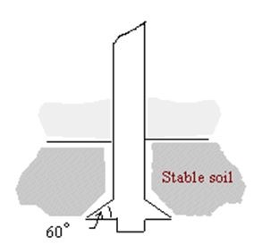
Fig 1.3. Under-reamed base enlargement to a bore-and-cast-in-situ pile
Classification of pile with respect to type of material
- Timber
- Concrete
- Steel
- Composite piles
Timber piles
Used from earliest record time and still used for permanent works in regions where timber is plentiful. Timber is most suitable for long cohesion piling and piling beneath embankments. The timber should be in a good condition and should not have been attacked by insects.
For timber piles of length less than 14 meters, the diameter of the tip should be greater than 150 mm. If the length is greater than 18 meters a tip with a diameter of 125 mm is acceptable. It is essential that the timber is driven in the right direction and should not be driven into firm ground.
As this can easily damage the pile. Keeping the timber below the ground water level will protect the timber against decay and putrefaction. To protect and strengthen the tip of the pile, timber piles can be provided with toe cover. Pressure creosoting is the usual method of protecting timber piles.
Concrete pile
Precast concrete Piles or Pre fabricated concrete piles : Usually of square (see fig 1.4 b), triangle, circle or octagonal section, they are produced in short length in one metre intervals between 3 and 13 meters. They are pre-caste so that they can be easily connected together in order to reach to the required length (fig 1.4 a) .
This will not decrease the design load capacity. Reinforcement is necessary within the pile to help withstand both handling and driving stresses. Pre stressed concrete piles are also used and are becoming more popular than the ordinary pre cast as less reinforcement is require.
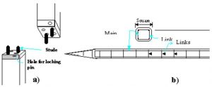
Fig 1.4a – Concrete pile connecting detail
Fig 1.4b – Squared pre-cast concert pile
The Hercules type of pile joint (Figure 1.5) is easily and accurately cast into the pile and is quickly and safely joined on site. They are made to accurate dimensional tolerances from high grade steels.
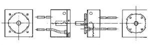
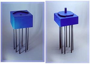
Fig 1.5 – Hercules type of pile joint
Driven and cast in place Concrete piles
Two of the main types used in the UK are: West’s shell pile : Pre cast, reinforced concrete tubes, about 1 m long, are threaded on to a steel mandrel and driven into the ground after a concrete shoe has been placed at the front of the shells. Once the shells have been driven to specified depth the mandrel is withdrawn and reinforced concrete inserted in the core. Diameters vary from 325 to 600 mm.
Franki Pile: A steel tube is erected vertically over the place where the pile is to be driven, and about a metre depth of gravel is placed at the end of the tube. A drop hammer, 1500 to 4000kg mass, compacts the aggregate into a solid plug which then penetrates the soil and takes the steel tube down with it. When the required depth has been achieved the tube is raised slightly and the aggregate broken out.
Dry concrete is now added and hammered until a bulb is formed. Reinforcement is placed in position and more dry concrete is placed and rammed until the pile top comes up to ground level.
Steel piles
Steel piles: steel/ Iron piles are suitable for handling and driving in long lengths. Their relatively small cross-sectional area combined with their high strength makes penetration easier in firm soil. They can be easily cut off or joined by welding. If the pile is driven into a soil with low pH value, then there is a risk of corrosion, but risk of corrosion is not as great as one might think. Although tar coating or cathodic protection can be employed in permanent works.
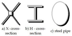
Fig 1.6 – Steel piles cross-sections
It is common to allow for an amount of corrosion in design by simply over dimensioning the cross-sectional area of the steel pile. In this way the corrosion process can be prolonged up to 50 years. Normally the speed of corrosion is 0.2-0.5 mm/year and, in design, this value can be taken as 1mm/year.
Composite piles
Combination of different materials in the same of pile. As indicated earlier, part of a timber pile which is installed above ground water could be vulnerable to insect attack and decay. To avoid this, concrete or steel pile is used above the ground water level, whilst wood pile is installed under the ground water level (see figure 1.7).
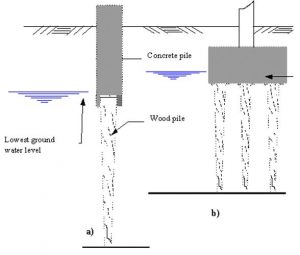
Fig 1.7 – Protecting timber piles from decay:
a) by pre-cast concrete upper section above water level.
b) by extending pile cap below water level
Classification of pile with respect to effect on the soil
A simplified division into driven or bored piles is often employed.
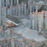
Driven piles
Driven piles are considered to be displacement piles. In the process of driving the pile into the ground, soil is moved radially as the pile shaft enters the ground. There may also be a component of movement of the soil in the vertical direction.
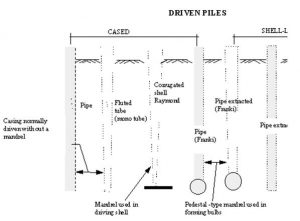
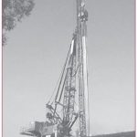
Fig 1.8 – Driven Piles
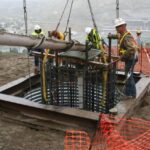
Bored piles
Bored piles(Replacement piles) are generally considered to be non-displacement piles a void is formed by boring or excavation before piles is produced. Piles can be produced by casting concrete in the void.
Some soils such as stiff clays are particularly amenable to the formation of piles in this way, since the bore hole walls do not requires temporary support except cloth to the ground surface. In unstable ground, such as gravel the ground requires temporary support from casing or bentonite slurry. Alternatively the casing may be permanent, but driven into a hole which is bored as casing is advanced.
A different technique, which is still essentially non-displacement, is to intrude, a grout or a concrete from an auger which is rotated into the granular soil, and hence produced a grouted column of soil.
There are three non-displacement methods: bored cast- in – place piles, particularly pre-formed piles and grout or concrete intruded piles.
The following are replacement piles:
- Augered
- Cable percussion drilling
- Large-diameter under-reamed
- Types incorporating pre caste concrete unite
- Drilled-in tubes
- Mini piles
More from my site
 Pile Capacity All Calculations Spreadsheet
- Why Use a Group of Piles Instead of a Single Pile in Foundations: An In-Depth Look
- What are Deep Foundation? The Common Types of Deep Foundation
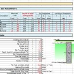
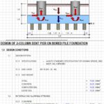
- Design Of Two-Column Bent Pier On Bored Pile Foundation Spreadsheet
- History Of Pile Foundation
- Construction Program Management – Decision Making and Optimization Techniques