Retaining Wall with Anchors Analysis and Design Spreadsheet
31 October 2018Retaining Wall with Anchors Analysis and Design Spreadsheet
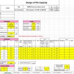
Retaining walls with anchors shall be dimensioned to ensure that the total lateralload, Ptotal, plus any additional horizontal loads, are resisted by the horizontal component of the anchor Factored Design Load Thi, of all the anchors and the reaction, R, at or below the bottom of the wall. The embedded vertical elements shall ensure stability and sufficientpassive resistance against translation. The calculated embedment length shall be the greater of that calculated by the Designer or Geotechnical Services.
Typical design steps for retaining walls with ground anchors are as follows:
Step 1 : Establish project requirements including all geometry, external loading conditions (temporary and/ or permanent, seismic, etc.), performance criteria, and construction constraints. Consult with Geotechnical Services for the requirements.
Step 2 : Evaluate site subsurface conditions and relevant properties of the in situ soil or rock; and any specifications controlled fill materials including all materials strength parameters, ground water levels, etc. This step is to be performed by Geotechnical Services.
Step 3 : Evaluate material engineering properties, establish design load and resistance factors, and select level of corrosion protection. Consult with Geotechnical Services for soil and rock engineering properties and design issues.
Step 4 : Consult with Geotechnical Services to select the lateral earth pressure distribution acting on back of wall for final wall height. Add appropriate water, surcharge, and seismic pressures to evaluate total lateral pressure. Check stability at intermediate steps during contruction. Geotechnical numerical analysis may be required to simulate staged construction. Consult Geotechnical Services for the task, should it be required.
Step 5 : Space the anchors vertically and horizontally based upon wall type and wall height. Calculate individual anchor loads. Revise anchor spacing and geometry if necessary.
Step 6 : Determine required anchor inclination and horizontal angle based on right-of-way limitations, location of appropriate anchoring strata, and location of underground structures.
Step 7 : Resolve each horizontal anchor load into a vertical force component and a force along the anchor.
Step 8 : Structure Design checks the internal stability and Geotechnical Services checks the external stability of anchored system. Revise ground anchor geometry if necessary.
Step 9 : When adjacent structures are sensitive to movements Structure Design and Geotechical Services shall jointly decide the appropriate level and method of analysis required. Revise design if necessary. For the estimate of lateral wall movements and ground surface settlements, geotechnical numerical analysis is most likely required. Consult with Geotechnical Services for the task, should it be required.
Step 10 : Structure Design analyzes lateral capacity of pile section below excavation subgrade.
Geotechnical Services analyzes vertical capacity. Revise pile section if necessary.
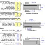
Step 11 : Design connection details, concrete facing, lagging, walers, drainage systems, etc.
Consult with Geotechnical Services for the design of additional drainage needs.
Step 12 : Design the wall facing architectural treatment as required by the Architect.